
Jia-Ning Han, Zhi-Qiang Fan, Zhen-Hua Zhang. Structure stability, magneto-electronic properties, and modulation effects of Fe3GeTe2 nanoribbons [J]. Acta Physica Sinica, 2019, 68(20): 208502-1
- Acta Physica Sinica
- Vol. 68, Issue 20, 208502-1 (2019)
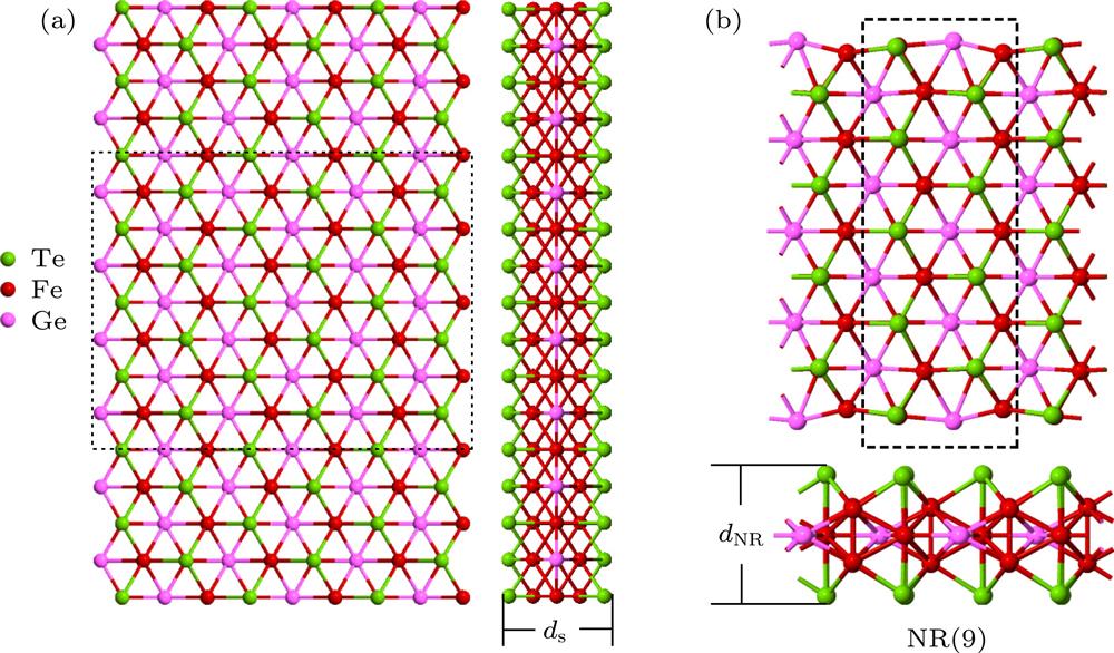
Fig. 1. (a) Top and side view of atomic structure for 2D FGT monolayer, the shaded region indicates the cutting nanoribbon NR(n ); (b) the FGT nanoribbon with width n = 9, and the black dashed-line box represents the unit cell of NR(9).
(a) 2D FGT单层原子结构的顶视图和边视图, 阴影部分表示所剪裁的纳米带NR(n ); (b)宽度n = 9时的FGT纳米带, 黑色虚线框代表纳米带的一个单胞
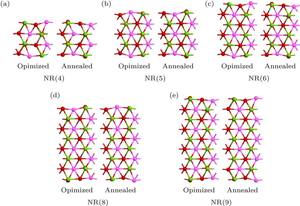
Fig. 2. The ribbon structures before and after annealing simulation: (a) NR(4); (b) NR(5); (c) NR(7); (d) NR(8); (e) NR(9).退火模拟前后的FGT纳米带的结构图 (a) NR(4); (b) NR(5); (c) NR(6); (d) NR(8); (e) NR(9)
Fig. 3. The spin-polarized charge density: (a) NR(4), (b) NR(5), (c) NR(6), (d) NR(8), and (e) NR(9), the isosurface value is set as 0.01|e |Å–3.
自旋极化电荷密度 (a) NR(4), (b) NR(5), (c) NR(6), (d) NR(8)和(e) NR(9), 等值面值取为0.01|e |Å–3
Fig. 4. The projected band structure for (a) NR(4), (b) NR(5), (c) NR(6), (d) NR(8), and (e) NR(9), respectively; (f) magnetic moment per magnetic atom for NR(n ) versus ribbon widths, where n represents the width of the FGT nanoribbons.
投影能带结构 (a) NR(4), (b) NR(5), (c) NR(6), (d) NR(8)和(e) NR(9); (f)不同宽度NR(n )的磁性原子的平均磁矩, 其中n 为FGT纳米带的宽度
Fig. 5. The DOS and PDOS for (a) NR(4), (b) NR(5), (c) NR(6), (d) NR(8), and (e) NR(9); (f) the spin polarity efficiency at the Fermi level (SPF) for ribbons with various different widths NR(n ), where n represents the width of the FGT nanoribbons.
不同FGT纳米带的总态密度(DOS)、投影态密度(PDOS)以及费米能级上的自旋极化率 (a) NR(4), (b) NR(5), (c) NR(6), (d) NR(8) 和 (e) NR(9); (f) 不同宽度纳米带NR(n )的在费米能级上自旋极化率SPF, 其中n 为FGT纳米带的宽度
Fig. 6. Strain effects: (a) The schematic for NR(9) applied by stretching strain, only the FM ground state is taken into account; (b) the DOS versus strains; (c) the spin polarity efficiency at the Fermi level SPF versus strains; (d) the magnetic moment (M ) and magnetize energy (E M) versus strains.
应变效应 (a) 对NR(9)施加拉伸应力的模型图, 仅铁磁基态下被考虑; (b)施加不同应变时的态密度(DOS)变化情况; (c)费米能级上的自旋极化率SPF 随应变的变化; (d)磁矩(M )和磁化能(E M)随应变的变化
|
Table 1.
The binding energy Eb (in eV/atom), magnetic energy EM (in meV /atom), and spin polarized efficiency SPF(%) for FGT nanoribbons, MM and HM represent the magnetic metal and half-metal, respectively.
FGT纳米带的结合Eb(单位: eV/atom), 磁化能EM (单位: meV/atom)和费米能级上的自旋极化率SPF(%), MM 和HM分别表示磁金属和半金属

Set citation alerts for the article
Please enter your email address
© Copyright 2018-2021 | Chinese Laser Press. All Rights Reserved 沪ICP备15018463号-20