This Letter presents a multi-hop relay visible light communication (VLC) system for maritime applications. Maritime VLC systems suffer from limited coverage distance due inherently to the usage of light-emitting diodes and photodetectors. The proposed system employs a multiple of decode-and-forward relays to extend coverage distance in maritime environments. The multi-hop relay based maritime VLC is analyzed under a maritime channel modeled by the JONSWAP spectrum and gamma–gamma distribution. It is found that the use of relays in maritime environments can extend the coverage distance significantly and also improve the performance. In addition, the performance of the system is analyzed using various combining techniques at the receiver to enhance the performance. The maximal ratio combining technique is found to provide superior link quality in maritime environments.
The illumination industry is witnessing a revolutionary advancement with the advent of light-emitting diodes (LEDs). Efficient LED-based lamps have replaced both incandescent and fluorescent lamps in indoor and outdoor lighting[1]. Light from LEDs can be modulated at a high speed, thus paving the way for communication. Visible light communication (VLC), a recently developed optical wireless communication technology, utilizes LED blinking to transmit data. The widespread use of LEDs in maritime applications presents a multitude of opportunities for visible light-based maritime communications[2–4]. The current maritime wireless communications rely predominantly on radio frequencies (RFs), which suffer from high cost with a low transmission speed and scarce operation spectrum. To overcome these limitations in maritime communications, VLC can be considered an alternate technology in maritime environments. One of the main challenges in VLC is to reduce the effect of atmospheric turbulence and sea surface movement[5], which can severely degrade the system performance, especially for a relatively long-distance maritime link.
For example, the work in Ref. [6] studies both serial (i.e., multi-hop transmission) and parallel (i.e., cooperative diversity) relaying coupled with amplify-and-forward and decode-and-forward (DF) modes. This outage probability analysis demonstrates that an impressive performance improvement is possible with the use of a single relay at a target outage probability of .
In Ref. [7], which studied the end-to-end performance of multi-hop free-space optical wireless systems over turbulence-induced fading channels for the case of channel state information-assisted relays, an accurate asymptotic performance analysis at high signal-to-noise ratio (SNR) values is presented.
Sign up for Chinese Optics Letters TOC. Get the latest issue of Chinese Optics Letters delivered right to you!Sign up now
In this Letter, a multi-hop DF relay-based VLC system is proposed as an efficient maritime link covering a longer distance with adequate performance in maritime environments under realistic sea state parameters and in various atmospheric turbulence conditions. To simplify the analysis of the proposed system, all the relays are considered equidistant from the source and the destination. The performance of the proposed multi-hop VLC system over maritime channels with DF relay is further improved using receiver diversity with combining techniques[8].
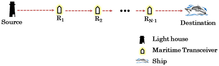
A maritime VLC multi-hop (maritime transceiver) communication system using DF relays is shown in Fig. 1. The intensity modulation/direct detection (IM/DD) link using on–off keying (OOK) is considered. The source is a lighthouse that communicates with the destination terminal through , optical transceivers. These act as relay nodes, all being equidistant. Assuming that there are hops and () DF relays between the source and the destination, is the received signal at hop and is given by where represents the information bits and is the optical-to-electrical conversion coefficient. Note that hop is referred to as the link between the ()th relay and the th relay. For , denotes the irradiance from the transmitter (lighthouse) and for through , represents the irradiance from the ()th relay at the th receiver, and is additive white Gaussian noise (AWGN) with zero mean and variance of . It can be assumed that the presence of ambient light in photodetectors (PDs) can be ignored under the Gaussian noise approximation[9]. Furthermore, although the ambient light is a major source of interference, particularly during the daytime, it can be significantly reduced using optical filters over the PDs in practical VLC implementations[9,10].
The equivalent end-to-end SNR, i.e., the SNR () at the receiver, can be written as[11]where is the instantaneous SNR at the th hop.
Assuming that all hops have the same statistical behavior, an approximated bit error rate (BER) of a DF-based multi-hop free space optics (FSO) can be calculated by[12]where is the BER at the th hop.
To simulate a maritime communication environment, we consider propagation impairments due to strong reflection from sea surface, random sea surface movements, and atmospheric turbulence. The sea conditions are modeled in the simulation according to the JONSWAP spectrum because the JONSWAP spectrum is more realistic than the Pierson–Moskowitz, Neumann, etc.[13]. The propagation impairments and sea conditions affect transmission reliability over wireless links, which in turn affect the packet delivery ratio at the network layer.
The JONSWAP spectrum is given by[14]where is acceleration of gravity and is the wave frequency; where is the intensity of the spectrum that relates to the wind speed and fetch length, is the wind speed at a height of 10 m above the sea surface, is the fetch length, and is the peak wave frequency, which is the maximum value that appears in the frequency spectrum. The peak enhancement function () and peak width parameter () are called the shape parameters. As these parameters change, the sea state spectrum changes: The typical spectral shape of the JONSWAP spectral density distribution is shown in Fig. 2. Figure 2 is plotted using a mean value of 3.3 for the peak enhancement factor and the parameters from Table 1[15,16].
Since the real-time data is not available for our study, we employ the sea state data generated from the JONSWAP spectrum. Table 1 shows the sea state parameters. The sea state conditions listed in Table 1 are a result of the reflective nature of the sea surface and the wave height, which are measures of the roughness of the sea parameters. In addition, the significant wave height represents the average of the highest one-third of all the waves present in an area of the sea surface[15].
For the present study, the analysis for lower sea states, i.e., sea states 1 to 3, was ignored, since these sea conditions are basically mild, resulting in negligible distortion at the receiving end. On the other hand, the signal distortion is severe at higher sea states resulting from the relatively high waves and rapidly moving wind. The scattering of the signal would be significant at these sea states, causing the signal to be extremely impaired at the receiver. To consider a realistic scenario for the present work, sea state 4 is considered throughout for the analysis.
As described earlier, a significant performance impairment factor for the optical link is the atmospheric turbulence phenomenon that causes the scintillation effect, resulting in fast irradiance fluctuations at the receiver. Therefore, the wireless optical channel acts like a fading channel and its behavior can be modeled accurately using the appropriate statistical distribution on the atmospheric turbulence conditions. For weak to strong turbulence conditions, a suitable statistical distribution for modeling the irradiance fluctuations is gamma–gamma[17]]. The probability density function (PDF) of the gamma–gamma distribution as a function of is given by[17]where is the modified Bessel function of the second kind of order , and represents the gamma function. If the optical radiation is assumed to be a plane wave, the two parameters and that characterize the irradiance fluctuation PDF are related to the atmospheric conditions by
The parameter is the Rytov variance, assuming plane wave propagation and is given by where is the link length, is the optical wave number, and is the altitude-dependent index of the refractive structure parameter determining the turbulence strength. Table 2 gives the normal gamma–gamma turbulence parameters in turbulent conditions[18].
Turbulence regime
Parameter
weak
moderate
strong
σl2
0.2
1.6
3.5
α
11.6
4.0
4.2
β
10.1
1.9
1.4
Table 2. Turbulence Parameters in Weak-to-Strong Turbulence Regimes
One of the possible methods of reducing atmospheric turbulence is the use of aperture averaging[18]. In aperture averaging, the receiver aperture needs to be far greater than the spatial coherence distance of the atmospheric turbulence in order to receive several uncorrelated signals. This condition is only achieved in FSO when the aperture size is in the order of centimeters, since the spatial coherence distance is in the order of centimeters[19]. Hence, we utilized a PD array whose area is ( PDs, each with an area of ) as shown in Fig. 3 and performed receiver diversity techniques. In order to exploit diversity gain over an array of PDs, three combining schemes were employed in the present work and compared in terms of performance: selection combining (SC), equal gain combining (EGC), and maximal ratio combining (MRC)[8].
To derive a closed-form analysis, we first develop a statistical model for the combined electrical SNRs at the receiver. Among the considered combining schemes, the SC is the simplest since it processes only one of the diversity apertures or specifically the aperture with the maximum received irradiance (or electrical SNR). Therefore, the selection is made according to The received signal and average SNR at the output of the SC receiver can be expressed as
For the case where EGC is implemented at the receiver, the received signal and SNR can be expressed as
In the case of MRC, the combined signal and SNR are given as
Simulations were conducted to investigate the link performance for the proposed shore-to-sea maritime VLC link employing multi-hop relays. Note that the sea parameters, the turbulence, and the AWGN were collectively considered as an impairment factor for the maritime VLC in the simulations. In addition, was first obtained from the simulations and the composite BER was obtained from Eq. (3). The simulations used the parameters shown in Table 3 and employed the OOK modulation. The DF relay-based maritime system with sea state 4 and gamma–gamma turbulence were considered. It is worth noting that the transmitted optical power from the relay was considered in accordance with the values defined in the International Association of Lighthouse Authorities’s manual[20].
Parameters
Values
Transmitted optical power (all LEDs) in lighthouse
Figure 4 shows the comparison of BER performances over each gamma–gamma turbulence condition at a larger distance between the transmitter and the receiver in a single-hop system. It is found that the BER of the system increases with the increase of the value of the Rytov variance (from weak to strong turbulence). It is also observed that the BER performances at a longer distance between the transmitter and the receiver are poor. Therefore, a few compensation techniques are required, such as a partially coherent beam, aperture averaging, adaptive optics, and spatial diversity[18].
Figure 4.Comparison of BER performance over each gamma–gamma turbulence strength.
Furthermore, we performed a comparative study with PD array-based diversity combining techniques. Figure 5 depicts the BER performance comparison among the combining techniques over sea state 4 and the weak turbulence condition in a single-hop system. Note that for the purpose of demonstrating the effectiveness of the proposed scheme, we employ these maritime conditions. In effect, these conditions are considered to prevail in most practical maritime situations. At an SNR value of 10 dB, the average BERs of the diversity combining techniques are better than , while the BER of the non-diversity scheme is just . For a fair comparison, an identical PD area of for all PDs was considered for the diversity schemes. By the same token, the PD area for the non-diversity scheme ( in Figs. 5 and 6) was also ensured to be , although it appears to be impractical.
Finally, Fig. 6 shows the BER performance relative to the number of hops between the transmitter and the receiver with the combining techniques. The distance between the transmitter and the receiver is set to 5 km. It is clear that there is an increasing gap in terms of the BER over the considered combining techniques as the number of hops increases. However, it is found that the proposed multi-hop relay-based maritime system with the MRC technique provides the best link quality under the maritime environments; it achieves a BER of approximately with 4 relays for the transmission. It should be noted that the proposed scheme would entail higher complexity due to the DF and the combining processes. Nonetheless, it is of paramount importance to provide increased coverage in the maritime environment; thus, the complexity would not be significantly detrimental.
In conclusion, a generalized multi-hop VLC system over maritime channels with DF relays is presented. The performance of the proposed multi-hop maritime VLC system is analyzed considering various noise parameters in maritime environments, such as sea states and gamma–gamma turbulence. Furthermore, in order to enhance the performance, the diversity combining techniques are utilized. It is found that the MRC scheme gives a superior BER performance at a 5 km distance with 4 relays installed equidistantly.
References
[1] N. Lourenco, D. Terra, N. Kumar, L. Alves, R. L. Aguiar. Proceedings of International Symposium on Communication Systems, Networks Digital Signal Processing, 1(2012).