Sung-Man Kim, Jongmyeong Choi, Hyunwoo Jung. Experimental demonstration of underwater optical wireless power transfer using a laser diode[J]. Chinese Optics Letters, 2018, 16(8): 080101
Copy Citation Text
We experimentally demonstrate an underwater optical wireless power transfer (OWPT) using a laser diode (LD) as a power transmitter. We investigate the characteristics of a solar cell and a photodiode (PD) as a power receiver. We optimize the LD, the PD, and the solar cell to achieve the maximum transfer efficiency. The maximum transfer efficiency of the back-to-back OWPT is measured as 4.3% with the PD receiver. Subsequently, we demonstrate the OWPT in tap and sea water. Our result shows an attenuation of 3 dB/m in sea water.
In recent years, wireless power transfer technology has attracted considerable attention and has been rapidly evolving from theories toward commercial products[1]. The existing wireless power transfer technologies may be broadly classified into non-radiative coupling-based transfer and radiative radio frequency (RF)-based transfer[2]. The non-radiative coupling-based transfer technologies include inductive coupling[3], magnetic resonance coupling[1], and capacitive coupling[4]. The transfer efficiency of the non-radiative coupling-based technologies is relatively high, so they have been widely commercialized in our daily appliances, such as a wireless smartphone charger. However, the effective transfer distances of the non-radiative coupling-based technologies are below several meters. Although the radiative RF-based transfer technologies can transfer power to a longer distance, the transfer efficiency decreases with the square of the distance[5]. Although RF-beamforming-based transfer technology was proposed to increase the transfer distance[6], there still exists a limit on the effective transfer distance. In addition, it causes electromagnetic interference (EMI) to other electronic devices.
To extend the transfer distance, optical wireless power transfer (OWPT) could be a suitable solution. OWPT is a wireless power transfer technology using light as the power deliverer. In OWPT, a light source is used at the transmitter site to convert electric power to optical power, and an optical power receiver, such as a solar cell, is used at the receiver site to convert the received optical power to electric power.
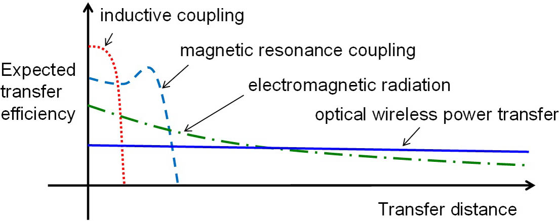
Unlike the RF beam, the size and the power of a laser beam can be maintained in a much longer distance. Therefore, the transfer efficiency of the OWPT using a laser is not easily degraded with distance. In addition, it does not cause EMI to existing radio communications. Figure 1 illustrates the expected DC-to-DC transfer efficiencies of the wireless power transfer technologies as a function of distance[7]. Although the transfer efficiency of the OWPT is lower than other technologies in the short distance, it is expected to be higher than other technologies in the long distance. Until now, there have been several researches on OWPT[8–13]. Most of them are based on a laser transmitter and a solar cell receiver, whereas a couple of OWPT works using a light-emitting diode (LED) transmitter have been demonstrated[8,9]. Although OWPT could be a suitable solution for long-distance wireless power transfer, there is only a limited amount of research toward this.
Sign up for Chinese Optics Letters TOC. Get the latest issue of Chinese Optics Letters delivered right to you!Sign up now
Figure 1.Expected transfer efficiencies of wireless power charge technologies as a function of transfer distance.
Meanwhile, recently, the demand for underwater robots has increased due to the rising interest in marine development. For underwater robots working for a long time, it could be efficient to charge the batteries wirelessly without replacing the batteries. However, the RF-based wireless power transfer is not efficient in the water, especially in the long distance over a meter, because the absorption of RF waves is severe in the water, whereas that of visible light is relatively low[14]. Thus, the OWPT using visible light could be a good candidate for long-distance underwater wireless power transfer. Although there have been several OWPT researches so far, it is hard to find an OWPT report in the underwater condition.
Therefore, in this study, we conduct an experimental study for a long-distance underwater OWPT over a meter. We investigate the DC-to-DC transfer efficiency of OWPT as a function of distance in tap and sea water. In the experiment, we use a laser diode (LD) as an optical power transmitter similarly in other conventional OWPT works; however, we demonstrate that both a photodiode (PD) and a solar cell can be used to receive optical power, differently from other conventional OWPT works. Subsequently, we compare the performance of the PD and the solar cell as the optical power receiver.
Figure 2 shows the structure of OWPT. At the transmitter site, an optical source is needed to convert from electric power to optical power because the most common form of the energy source is electric power. The optical source can be a laser, an LED, etc. When the electric power delivered to the optical source is , and the optical output power emitted by the optical source is , the electric-to-optic (E/O) power conversion ratio of the optical source can be defined as
After the optical source, a suitably designed optic device made of lenses or mirrors can be optionally used to direct the optical power to a desired direction. When the optical power directed to the desired direction is , the directivity ratio of the transmitter can be defined as
At the receiver site, a suitably designed optic device made of lenses or mirrors can also be optionally used to increase the acceptance ratio of the optical power receiver. When the total optical power that arrived at the receiver site is , and the optical power accepted by the optical power receiver is , the acceptance ratio of the optical power receiver can be defined as
After the optic device, an optical power receiver, such as a solar cell or a PD, is used to convert the received optical power to electric power. When the output electric power of the optical power receiver is , the optic-to-electric (O/E) power conversion ratio of the optical power receiver can be defined as
If we consider the loss of light in the transfer medium and assume the symbol is the attenuation parameter of the light per meter, the optical power arriving at the receiver site can be expressed as where is the transfer distance in meters. Therefore, the total DC-to-DC transfer efficiency of the OWPT, , can be expressed as
Figure 3 shows the block diagram and the photograph of the experimental setup. In the experiment, a low-cost 100 mW red LD was used for the light source. The peak wavelength of the LD was measured as 661 nm. To increase the E/O conversion efficiency of the LD to be as high as possible, optimization of the LD is required. To optimize the LD, we investigate the characteristics of the LD.
Figure 3.(a) Block diagram and (b) photograph of the experimental setup for underwater OWPT. The transmitter is located at the left side in the block diagram, whereas it is at the right side in the photograph.
Figure 4 shows the optical output power and the E/O conversion efficiency as a function of the operating voltage of the LD. The E/O conversion efficiency of the LD is the highest, 47.4%, when the operating voltage is 2.9 V. The electrical current is 77.1 mA, and the optical output power is 106 mW at the point. The interesting point is that the highest E/O conversion efficiency point is before the power saturation region, as shown in Fig. 4. After the optical output power reaches the maximum value, the E/O conversion efficiency decreases, as shown in Fig. 4. This result implies that we have to operate the LD slightly below the maximum output power to obtain the highest E/O conversion efficiency.
Figure 4.Optical output power and E/O conversion efficiency of the LD.
Similarly to the transmitter site, the optimization of the optical power receiver is required to obtain the maximum O/E conversion efficiency at the receiver site. In this study, we investigated and compared two kinds of optical power receivers, a solar cell and a PD. First, we measured the characteristics of a PD as an optical power receiver. In this experiment, a Vishay BPV10 PD was used. The PD is a low-cost silicon positive-intrinsic-negative (PIN) PD that has a diameter of 5 mm, a sensitive area of , and a sensible spectral range of . The spectral sensitivity is the highest at near 900 nm, and the quantum efficiency is 72% at 950 nm. However, the sensitivity of the PD in this experiment may be below the specification value because the light source of the experiment operates at 661 nm. If we roughly estimate the quantum efficiency of the PD according to the spectral sensitivity data of the PD, it might be about 45% at 661 nm. Figure 5 shows the voltage–current graph of the PD by changing the load resistance when the LD is operating at the highest E/O conversion efficiency (i.e., when the optical output power is 106 mW), and the transfer distance is 0 m. When the load resistance is , the output electric power, calculated by the multiplication of the voltage and the current, is the maximum value of 8.12 mW. Therefore, the optimized O/E conversion efficiency of the PD at this optical power is . Here, we mention that the sensitivity area of the PD is small, so there was a possibility of the light leakage in the PD, although we did our best to focus the light on the PD using a lens. This might reduce the O/E conversion efficiency of the PD.
Figure 5.Voltage–current graph of the PD by changing the load resistance when the LD is operating at the most efficient condition.
We also investigated the characteristics of a solar cell as the optical power receiver. In the experiment, a low-cost silicon solar cell was used. The size of the solar cell is . Figure 6 shows the voltage–current graph of the solar cell by changing the load resistance when the LD is operating at the highest E/O conversion efficiency, and the transfer distance is 0 m. When the load resistance is , the output electric power is the maximum value of 8.74 mW. Therefore, the optimized O/E conversion efficiency of the solar cell is at this optical power. Here, we mention that the beam pattern of the LD is circular, whereas that of the solar cell is rectangular, and, therefore, the edge of the solar cell could not receive the optical power. This might reduce the O/E conversion efficiency.
Figure 6.Voltage–current graph of the solar cell by changing the load resistance when the LD is operating at the most efficient condition.
Figure 7 shows the O/E conversion efficiency of the PD and the total back-to-back transfer efficiency as a function of LD output power. This result implies that the O/E conversion efficiency of the PD is a function of incident optical power. We think that the reason of decreasing O/E conversion efficiency with the incident optical power after 60 mW is that there is a limit in the acceptable optical power in the PD. Therefore, we think that there is a possibility of increasing the total transfer efficiency if we use another PD that can accept higher optical power. Using the PD receiver, the maximum back-to-back transfer efficiency is 4.3% when the LD optical power is 50 mW, at which the E/O conversion efficiency of the LD is 41.0%, and the O/E conversion efficiency of the PD is 10.4%.
Figure 7.E/O conversion efficiency of the LD, O/E conversion efficiency of the PD, and the total back-to-back transfer efficiency as a function of LD optical power.
Figure 8 shows the O/E conversion efficiency of the solar cell and the total back-to-back transfer efficiency as a function of LD output power. This result implies that the O/E conversion efficiency of the solar cell increases with the incident optical power up to a certain level and then is saturated, which corresponds with our previous result[15]. Using the solar cell receiver, the maximum back-to-back transfer efficiency is 4.0% when the LD optical power is 130 mW, at which the E/O conversion efficiency of the LD is 45.5%, and the O/E conversion efficiency of the solar cell is 8.7%. The experimental results at the maximum back-to-back transfer efficiency with each type of receiver are summarized in Table 1.
Type of Receiver
Parameter
PD
Solar Cell
LD output power
50 mW
130 mW
E/O efficiency of the LD (CE/O)
41.0%
45.5%
O/E efficiency of the receiver (CO/E)
10.4%
8.7%
Optimum load resistance of the receiver
39Ω
390Ω
Total transfer efficiency (EBtoB)
4.3%
4.0%
Table 1. Parameter Values at the Maximum Transfer Efficiencies with the PD and the Solar Cell Receivers
Figure 8.E/O conversion efficiency of the LD, O/E conversion efficiency of the solar cell, and the total back-to-back transfer efficiency as a function of LD optical power.
In the back-to-back transfer, we can assume that , because the optical source is an LD, and all of the optical power of the LD is directed to the optical power receiver. Also, we can also assume that , because all of the arrived optical power is received by the optical power receiver. The transfer distance is , because it is a back-to-back transfer. Therefore, from Eq. (6), the DC-to-DC transfer efficiency of the back-to-back OWPT can be expressed as
According to our experimental experience, the E/O conversion efficiency of a high-power LD is higher than that of a low-power LD. The LD used in the previous work was a 3 mW LD, and the LD used in the current work is a 100 mW LD. This is why the E/O conversion efficiency of the LD in this work is better than in our previous work[8]. In addition, as we mentioned, the O/E conversion efficiency of the solar cell increases with the input optical power up to a certain level. This is why the O/E conversion efficiency of the solar cell in this work is better than in our previous work[8]. Therefore, we think that there is still a possibility of improving the E/O and O/E conversion efficiencies more if we increase the LD power in future work.
To investigate the propagation characteristics in the water, we measured the DC-to-DC transfer efficiencies of the OWPT as a function of transfer distance in air, tap water, and sea water, as shown in Fig. 9. Because the O/E conversion efficiency of the solar cell receiver is better than that of the PD receiver, only the solar cell receiver is used in this experiment. The tap water was obtained in Busan, South Korea, and the sea water was obtained in the Gwanganli beach, Busan, South Korea. In the transfer distance longer than 4 m, the LD beam size spread farther than the lens used for focusing the transferred light to the optical power receiver. This is why the experimental data ended at 4 m in Fig. 9. Therefore, we need to consider the divergence of the laser beam in the real applications.
Figure 9.Transfer efficiencies of the underwater OWPT as a function of transfer distance. The dashed line is the analytic graph of the sea water with the attenuation parameter of .
Our main concern is the sea water case because our target application is charging an underwater robot working in the sea. Fortunately, the data in Fig. 9 seems to be enough to obtain the attenuation parameter of the sea water. From Eq. (5) and the data of Fig. 9, we obtained the attenuation parameter of the sea water, , which is equal to 3.0 dB/m. Therefore, the DC-to-DC transfer efficiency of the seawater OWPT can be expressed as where is the transfer distance in meters.
Figure 10 shows the expected efficiency of the seawater OWPT by using Eq. (8). In Fig. 10, we assume that all of the light from the LD is transferred to the target optical power receiver. With this assumption, . Also, because and , Eq. (8) can be shortened to
Figure 10.Expected transfer efficiency of the seawater OWPT as a function of transfer distance by using the measured attenuation parameter.
In Fig. 10, it is estimated that 1% and 2% OWPT efficiencies can be achieved within the transfer distance of 2 and 1 m, respectively.
It is known that the attenuation of blue light is less than red light in pure water[14], so we investigated the possibility of improving the propagation characteristic of OWPT using a blue laser. However, according to our experimental trial, the E/O conversion efficiency of a blue LD is lower than a red LD, and the O/E conversion efficiency of a solar cell in blue light is lower than in red light. Consequently, the total transfer efficiency of the OWPT using a blue LD was lower than the red LD case.
In this study, we experimentally demonstrated an underwater OWPT using an LD transmitter and two types of optical power receivers: a solar cell and a PD. A mathematical expression for the transfer efficiency of OWPT was also derived. The maximum E/O conversion efficiency of the LD was 47.4% with the optimization of the operating voltage. The maximum O/E conversion efficiencies of the PD and the solar cell were 10.4% and 8.7%, respectively, with the optimization of the load resistance and incident optical power. However, the optimum points of the LD and the receivers are different, so we calculated the transfer efficiency by multiplying the efficiencies of the LD and the receivers at each power level. Consequently, the maximum back-to-back OWPT efficiency was 4.3% with the PD receiver.
The underwater OWPT experiment shows an attenuation of 3.0 dB/m in the seawater. Therefore, we can deliver power wirelessly with a transfer efficiency of 2% up to 1 m in the seawater. Although currently the transfer efficiency seems not to be enough for real applications, there is a possibility to improve the transfer efficiency more in the future, and this work might be a first step for the underwater OWPT.
[11] S. Raavi, B. Arigong, R. Zhou, S. Jung, M. Jin, H. Zhang, H. Kim. Proceedings of Symposium on Wireless and Microwave Circuits and Systems (WMCS), 1(2013).
[12] C. Pani, O. Ray, A. Ghosh, Z. Qadir, M. M. Sarkar, W. Reja. Proceedings of International Conference on Advances in Computing, Communication, and Automation (ICACCA), 1(2016).
[13] A. Saha, S. Iqbal, M. Karmaker, S. F. Zinnat, M. T. Ali. Proceedings of Annual International Conference of the IEEE Engineering in Medicine and Biology Society (EMBC), 1978(2017).
Sung-Man Kim, Jongmyeong Choi, Hyunwoo Jung. Experimental demonstration of underwater optical wireless power transfer using a laser diode[J]. Chinese Optics Letters, 2018, 16(8): 080101