Abstract
Electromagnetic vortices, which describe the orbital angular momentum (OAM) carrying waves with a helical phase front, have recently attracted much interest in a radio frequency domain due to their potential applications in many diverse areas. In an OAM-based scenario, the antenna for OAM mode multiplexing/demultiplexing plays an essential role in controlling the overall system performance. In this paper, we demonstrated theoretically and experimentally an easily realized OAM antenna based on the traveling-wave circular loop structure for efficiently multiplexing/demultiplexing multiple OAM modes; in addition, its general propagation characteristics including the polarization, divergence, and radiation pattern are mathematically analyzed. Schemes for antenna size reduction and various radiation pattern manipulations have also been discussed to realize a more flexible and compact system.1. INTRODUCTION
Since the seminal work by Poynting [1], it has been known for more than a century that electromagnetic (EM) waves carry not only linear momentum but also angular momentum (AM), which means that some EM waves transfer rotational motion as they travel in free space, giving rise to the phenomenon of EM vortices [2]. Such waves containing helical phase fronts carry orbital angular momentum (OAM). Different from the spin angular momentum characterizing the polarization states of the EM wave, OAM describes the field spatial distribution, namely, the helical-shaped wavefront of , where is an arbitrary integer, called the OAM mode number and is the transverse azimuthal angle. There exists a phase undefined area at the propagating axis where the intensity of the EM field vanishes (for nonzero ), thus leading to the doughnut-shaped radiation pattern of the OAM-carrying waves [3].
Although OAM in the optical domain has been intensely investigated with the help of the Laguerre–Gaussian beams since the 1990s [3–5], OAM in radio frequency (RF) is still a new field. The first theoretical research on RF OAM, which demonstrated the feasibility of OAM-based wireless communication systems, was performed in 2007 [6], followed by the first experimental verification in 2012 [7]. Recently, based on the unique propagation characteristics of RF EM vortices, the applications of RF OAM have been theoretically and experimentally proposed in various areas. For instance, in a near-field line-of-sight free-space scenario, RF OAM multiplexing becomes an efficient space division multiplexing approach which can achieve a near maximum capacity gain without increasing the digital signal processing complexity at the receiving end [7–10]. Moreover, by detecting the echo signal of OAM waves, the structure or motion of a target can be reconstructed. This leads to the development of remote sensing as well as the research on microwave staring imaging [11,12], which would pave the way for applying OAM on the development of novel information-rich radar.
One of the key components determining the overall performance of an OAM-based system is the antenna for generating OAM-carrying waves. Therefore, it is of great importance to design an OAM antenna with an easily realized structure as well as the capability of efficiently multiplexing/demultiplexing multiple OAM modes. Typically, a plane or spiral phase plate [13,14] or a helical parabolic antenna [7,15] with dedicated modifications would be easy ways to generate OAM waves due to their simple structures. However, there exists the challenge of radiating waves with multiple OAM modes through a single aperture. A uniform circular array is another way to simultaneously radiate multiple OAM waves. Yet with the number of the OAM modes increasing, the implementation of its feeding network would be of great complexity and not cost effective as it requires a precise phase shift in each antenna element for each OAM mode [16], making it not a preferable choice in practical applications. To find an easy realization scheme for multiple OAM mode generation, we theoretically and experimentally demonstrated a traveling-wave circular loop radiator of simple structure to generate OAM modes of in RF domain [17,18]. Further, by concentrically stacking multiple radiators, efficient multiplexing/demultiplexing of much more intensive OAM modes is realized [19].
Sign up for Photonics Research TOC. Get the latest issue of Photonics Research delivered right to you!Sign up now
In this paper, we will highlight the simple scheme for generation of OAM waves based on the traveling-wave circular loop structure. In Section 2, the mathematical model of a circular loop current is described and the general propagation characteristics, including the polarization and the divergence of the generated OAM-carrying waves, are analyzed. In Section 3, we derive the radiation fields of the traveling-wave circular loop radiator, which could be viewed as a magnetic-type circular loop current as discussed in Section 2. A brief review of our previous work of generating 60 GHz millimeter waves with dual OAM modes of using one radiator is given. Further, by integrating two concentrically stacked radiators of and , respectively, a four-OAM-mode antenna is constructed at the operating frequency of 10 GHz. In Section 4, to manipulate the propagation characteristics as well as reduce the physical size of the radiator, the dielectric-filled radiators with different permittivities are demonstrated through both mathematical analysis and simulating results. Finally, a brief summary is given in Section 5.
2. MATHEMATICAL MODEL AND PROPAGATION CHARACTERISTICS OF A CIRCULAR LOOP CURRENT
Figure 1(a) shows the mathematical model of a circular loop with a current distribution of , in which is the azimuthal angle; is termed the phase distribution parameter, that is, the current phase increases times one loop; and is the constant magnitude of either a electric current or a magnetic current.
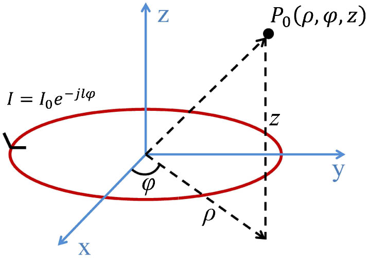
Figure 1.Mathematical model of the circular loop current of . represents the constant magnitude of either an electric current or a magnetic current.
According to our previous work [20], the approximate description of the radiation fields in cylindrical coordinates of an electric-type circular loop current is where ; ; is the radius of the circular loop current; ; and . Clearly, all the field components have a phase factor of , which is the general characteristic of the OAM-carrying waves. According to Eqs. (1) and (2), the radiation fields of a magnetic-type circular loop current would be derived using the duality principle [2].
To evaluate the evolution of the polarization characteristics of the generated vortices wave, the amplitude and phase of the axial ratio, namely, , are calculated: where . Due to the cylindrical symmetry of the radiated field, calculating the polarization state in the plane, , as a function of ranging from 0° to 90° is enough for general analysis. In the paraxial region ( and ), we have ; consequently, the amplitude of is nearly 1 with a phase of , that is, the twisted wave is almost right-handed circularly polarized. For (), we get , that is, it is tangential linear polarization. Since the magnitude of is not a constant while changes [20], a variety of polarization states would arise. With ranging from 0° to 90°, the whole evolution of the polarization states of the twisted wave is calculated and described in Fig. 2.
![Evolution of the polarization states for the twisted radio waves with increasing radius of θ ranging from 0° to 90°. Reprinted with permission from [20]. All rights reserved.](/Images/icon/loading.gif)
Figure 2.Evolution of the polarization states for the twisted radio waves with increasing radius of ranging from 0° to 90°. Reprinted with permission from [20]. All rights reserved.
Further, to characterize the divergence characteristic of the OAM-carrying waves with different phase distribution parameter of , the link budgets of a communication system based on the traveling-wave circular loop radiator are evaluated. In the numerical simulation, the transmitter and receiver aperture are both set to , that is, , where corresponds to the wavelength of 3 cm at the operating frequency of 10 GHz. is set to 1 for general analysis. The total link budget, , at a transmission distance of for OAM modes of would be
Based on the formulation [Eq. (4)], we show in Fig. 3 the link budgets computed for , 2, 3, 4, and 5, respectively, as a function of the transmission distance of ranging from to . As anticipated, the link budget asymptotically tends to straight lines of slope dB/decade. It is consistent with an attenuation of , which has already been proved in [21,22]. Consequently, it would be concluded that for the wave with OAM mode of propagating in free space, one should observe the approximately linear -scaling of the wave divergence in the far-field.
Figure 3.Link budgets of , 2, 3, 4, and 5, respectively. ; ; and .
3. MULTIPLE OAM MODES GENERATION BASED ON THE TRAVELING-WAVE CIRCULAR LOOP STRUCTURE
Based on Section 2, a metallic cavity traveling-wave circular loop radiator, made by looping a section of rectangular waveguide around an axis and loading a ring-slot on its narrow wall, could be viewed as a magnetic-type of the circular loop current and is able to generate OAM-carrying waves, as seen from Fig. 4(a). The radiator with an outer radius and an inner radius is operated in the transverse magnetic mode of . The wave number in the cavity is defined as where is the operating frequency, is the magnetic permeability of vacuum, and is the dielectric permittivity, , corresponding to a vacuum-filled radiator.
Figure 4.(a) Radiator with a ring-slot loaded on its narrow wall. The angle between two feeding ports (EPA and EPB) is . The outer radius and the inner radius of the radiator are and , respectively. (b) Explosion view of the metal resonator based parabolic antenna. Reprinted with permission from [9]. All rights reserved.
The electric and magnetic fields in the coaxial cavity can be obtained from solutions of the Helmholtz equations defined as follows [23]:
The Borgnis scalar functions and are applied for the solution of the above equation: where and are the order Bessel function and order Neumann function, respectively. On account of Eq. (7) and the boundary conditions of the mode, the eigenfunction can be derived:
The proposed radiator could be viewed as a magnetic-type circular loop current as described in Section 2; the main component of the radiation field, , is calculated as follows: where is the wave number in the air, and is a constant associated with the radiator configuration.
In order to excite a travelling wave in the radiator, two feeding ports with the same signal amplitude but of 90° phase difference are used, namely, EPA and EPB in Fig. 4(a). The angle between the two feeding ports is ,
Employing such feeding, a clockwise or anticlockwise traveling-wave distributed field can be excited in the ring resonator depending on the phase difference of between the two feeding ports.
Based on the structure depicted in Fig. 4(a), further combined with a waveguide 90° hybrid coupler as the phase-shift network and a ring focus parabolic reflector for favorable directivity, a two-OAM-mode antenna is designed to generate the millimeter-wave dual OAM waves with at the operating frequency of 60 GHz, seen from Fig. 4(b). By using a pair of such antennas, a 60 GHz millimeter-wave communication link with two separated OAM channels was experimentally demonstrated over 1.4 m [9].
In order to realize a much more intensive OAM mode multiplexing/demultiplexing system, a scheme of using multiple concentrically stacked radiators is proposed. Dual traveling-wave ring-slot radiators of and are used to generate four OAM modes at the operating frequency of 10 GHz. The phase-shift network can also be simply achieved by connecting each radiator with a commercial 90° hybrid coupler. A subreflector has been introduced to realize the double-reflector structure for a higher directivity. The designed model of the four-OAM-mode antenna is given in Fig. 5.
Figure 5.(a) Simulated four-OAM-antenna model. (b) Partially enlarged sectional view of the dual concentrically stacked radiators where and are two pairs of feeding ports for generating and , respectively, and the angle, , between the two feeding ports is 135° and 90° for and , respectively.
The simulated -parameters are grouped in Fig. 6. Lower -parameters mean a better system performance. It is seen that, at the operating frequency, the return losses are more than 20 dB and the isolations are all lower than .
Figure 6.-parameters of the four-OAM-mode antenna. in (a) and in (b) indicate the reflection and isolation, respectively.
The near-field radiation patterns including the phase and intensity distribution of the main electric component are simulated and grouped in Figs. 7(a)–7(d) and 7(e)–7(h) for OAM modes of , and , respectively, from left to right.
Figure 7.Simulated near-field radiation patterns for OAM modes of , and , respectively, from left to right. (a)–(d) Simulated transverse phase patterns. (e)–(h) Simulated transverse intensity patterns.
The simulated far-field results show that the directional angle, directivity, and 3 dB angular width of the main lobe for are 2.4°, 21.0 dBi, and 2.8°, respectively. For , they are 4.5°, 21.9 dBi, and 3.6°, respectively.
In fact, using the design idea of concentrically stacking radiators, more than four OAM waves can be generated. However, a higher manufacturing complexity as well as an enhanced intermode crosstalk would be taken into consideration. Consequently, an appropriate trade-off between the system performance and the realization complexity should be dealt with in practical applications.
4. MANIPULATING THE PROPAGATION CHARACTERISTIC OF VORTICES WAVES
To realize the control of the propagation characteristics and the physical size of the traveling-wave circular loop radiator, we start from Eq. (10). The normalized radiation pattern can be described as
Obviously, for a fixed frequency , the radiation characteristic of the generated vortex beam is determined by the outer radius of as well as the operating OAM mode of . According to Eq. (12), the angle of maximum gain would be defined as
As for a given state , if is small enough and would not exceed the position of the first peak of the order Bessel function, will be obtained at . As shown by the red line of Fig. 8, the radiation amplitude will increase monotonously with while and decrease monotonously while . However, if exceeds the position of the first peak of the order Bessel function, will increase nonmonotonously with , and there is more than one peak value of the radiation amplitude, as shown by the green, black, and blue curves in Fig. 8.
Figure 8.Normalized radiation pattern of as a function of different outer radius of (mm) at an operating frequency of 10 GHz.
To verify the mathematical analysis in Section 3, two coaxial cavities, where one is filled with air () and the other is filled with dielectric medium (), are carefully designed. The schematics are shown in Fig. 9, and their outer radiuses, at a frequency of 10 GHz, are 44.6 and 14.3 mm, respectively. The simulated far-field patterns of these two cavities are shown in Fig. 10. It can be seen that the main lobe direction of the air-filled cavity is about 58° and the 3 dB angular width is about 45°, while those of the dielectric-filled cavity are 90° and 65°, respectively. These results are in agreement with the analysis of Eq. (13) and Fig. 8. It is seen that OAM-carrying beams with different radiation patterns can be achieved by changing the antenna size. Seen from Fig. 11, the electric fields of the two cases are both in accord with the OAM mode of , that is, the spiral phase distribution of . Compared to the air-filled radiator, the physical size of the radiator filled with dielectric has been sharply reduced near 89.7%.
Figure 9.Schematics (cross section of plane) of the two cavities. (a) Air-filled cavity. (b) Dielectric-filled cavity.
Figure 10.Far-field radiation patterns of the two radiators. (a) Air-filled radiator. (b) Dielectric-filled radiator.
Figure 11.Electric fields (real part) of the generated vortices waves with OAM mode of at plane. (a) Air-filled radiator. (b) Dielectric-filled radiator.
By comparing the two cavities, we have shown that it is possible to control the radiation characteristic of OAM waves since the radiation of the coaxial cavity is decided by the outer radius , and the propagation property can be easily manipulated by choosing a proper dielectric permittivity . Moreover, we can obtain a size-reduced radiator, as indicated by a dielectric-filled antenna design.
5. SUMMARY
In this paper, through both the theoretical analysis and the experimental results, we demonstrated a simple method to generate RF vortex waves by utilizing the traveling-wave ring-slot structure. The general propagation characteristics, including the polarization, the divergence, and the radiation pattern, are also discussed. Based on the theoretical analysis, a metallic cavity radiator with dual OAM modes is successfully designed and, further, multi-OAM-mode generation is realized by concentrically stacking multiple radiators. To manipulate the propagation characteristics and the physical size of the radiator, a coaxial dielectric cavity with a proper dielectric permittivity is proposed. Numerical and simulation results show that it is possible to achieve not only a size-reduced radiator but also to control the radiation pattern of the generated vortex wave. These works would potentially benefit the OAM-based applications, such as RF communication, imaging, and motion detection, with an easily realized and size-reduced system.
References
[1] R. Loudon, C. Baxter. Contributions of John Henry Poynting to the understanding of radiation pressure. Proc. Royal Soc. London A, 468, 1825-1838(2012).
[2] J. D. Jackson. Classical Electrodynamics(1999).
[3] L. Allen, M. W. Beijersbergen, R. Spreeuw, J. Woerdman. Orbital angular momentum of light and the transformation of Laguerre–Gaussian laser modes. Phys. Rev. A, 45, 8185-8189(1992).
[4] G. Gibson, J. Courtial, M. Padgett, M. Vasnetsov, V. Pas’ko, S. Barnett, S. Franke-Arnold. Free-space information transfer using light beams carrying orbital angular momentum. Opt. Express, 12, 5448-5456(2004).
[5] A. M. Yao, M. J. Padgett. Orbital angular momentum: origins, behavior and applications. Adv. Opt. Photon., 3, 161-204(2011).
[6] B. Thidé, H. Then, J. Sjoholm, K. Palmer, J. Bergman, T. D. Carozzi, Y. N. Istomin, N. H. Ibragimov, R. Khamitova. Utilization of photon orbital angular momentum in the low-frequency radio domain. Phys. Rev. Lett., 99, 087701(2007).
[7] F. Tamburini, E. Mari, A. Sponselli, B. Thidé, A. Bianchini, F. Romanato. Encoding many channels on the same frequency through radio vorticity: first experimental test. New J. Phys., 14, 033001(2012).
[8] O. Edfors, A. J. Johansson. Is orbital angular momentum (OAM) based radio communication an unexploited area?. IEEE Trans. Antennas Propag., 60, 1126-1131(2012).
[9] X. Hui, S. Zheng, Y. Chen, Y. Hu, X. Jin, H. Chi, X. Zhang. Multiplexed millimeter wave communication with dual orbital angular momentum mode antennas. Sci. Rep., 5, 10148(2015).
[10] Y. Yan, G. Xie, M. P. J. Lavery, H. Huang, N. Ahmed, C. Bao, Y. Ren, Y. Cao, L. Li, Z. Zhao, A. F. Molisch, M. Tur, M. J. Padgett, A. E. Willner. High-capacity millimetre-wave communications with orbital angular momentum multiplexing. Nat. Commun., 5, 4876(2014).
[11] M. P. Lavery, F. C. Speirits, S. M. Barnett, M. J. Padgett. Detection of a spinning object using lights orbital angular momentum. Science, 341, 537-540(2013).
[12] K. Liu, Y. Cheng, Z. Yang, H. Wang, Y. Qin, X. Li. Orbital-angular-momentum-based electromagnetic vortex imaging. IEEE Antennas Wireless Propag. Lett., 14, 711-714(2015).
[13] M. Beijersbergen, R. Coerwinkel, M. Kristensen, J. Woerdman. Helical-wavefront laser beams produced with a spiral phaseplate. Opt. Commun., 112, 321-327(1994).
[14] R. Niemiec, C. Brousseau, K. Mahdjoub, O. Emile, A. Ménard. Characterization of an OAM flat-plate antenna in the millimeter frequency band. IEEE Antennas Wireless Propag. Lett., 13, 1011-1014(2014).
[15] E. Mari, F. Spinello, M. Oldoni, R. A. Ravanelli, F. Romanato, G. Parisi. Near-field experimental verification of separation of OAM channels. IEEE Antennas Wireless Propag. Lett., 14, 556-558(2015).
[16] A. Tennant, B. Allen. Generation of OAM radio waves using circular time-switched array antenna. Electron. Lett., 48, 1365-1366(2012).
[17] S. Zheng, X. Zhang, X. Jin, H. Chi. Orbital angular momentum generation using a circular wire loop antenna. International Photonics and OptoElectronics Meetings, OF3A.1(2014).
[18] S. Zheng, X. Hui, X. Jin, H. Chi, X. Zhang. Generation of OAM millimeter waves using traveling-wave circular slot antenna based on ring resonant cavity. IEEE International Conference on Computational Electromagnetics (ICCEM), 239-240(2015).
[19] W. Zhang, S. Zheng, Y. Chen, X. Jin, H. Chi, X. Zhang. Orbital angular momentum based communications with partial arc sampling receiving. IEEE Commun. Lett., 20, 1381-1384(2016).
[20] S. Zheng, X. Hui, X. Jin, H. Chi, X. Zhang. Transmission characteristics of a twisted radio wave based on circular traveling-wave antenna. IEEE Trans. Antennas Propag., 63, 1530-1536(2015).
[21] D. K. Nguyen, O. Pascal, J. Sokoloff, A. Chabory, B. Palacin, N. Capet. Antenna gain and link budget for waves carrying orbital angular momentum. Radio Sci., 50, 1165-1175(2015).
[22] M. J. Padgett, F. M. Miatto, M. P. Lavery, A. Zeilinger, R. W. Boyd. Divergence of an orbital-angular-momentum-carrying beam upon propagation. New J. Phys., 17, 023011(2015).
[23] C. Sheppard, S. Saghafi. Transverse-electric and transverse-magnetic beam modes beyond the paraxial approximation. Opt. Lett., 24, 1543-1545(1999).


