Ruma Debnath, Digvijay Singh Hada, Susheel Kumar Beda, Ardhendu Saha. Electro-optically tunable self-focusing and self-defocusing in KTP crystals by a cascaded second-order process[J]. Chinese Optics Letters, 2016, 14(12): 121902
Copy Citation Text
We report the transformation of a linear electro-optically tunable non-phase-matched second-order nonlinear process into a cascaded second-order nonlinear process in a bulk KTP crystal to generate the effect of electro-optically tunable Kerr-type nonlinearity. By applying an electric field on the plane, parallel to the -axis of the crystal, phase mismatch is created, which introduces a nonlinear phase shift between the launched and reconverted fundamental waves from the generated second harmonic wave. Due to the nonuniform radial intensity distribution of a Gaussian beam, a curvature will be introduced into the fundamental wavefront, which focuses or defocuses the incident beam while propagating through the crystal.
Cascaded second-order nonlinearity has been investigated in various crystals so far by applying different methods; it has vital applications in self-focusing and self-defocusing[1], spatial solitons[2], all-optical switching, mode locking, transistor action[3], high-speed optical shutters[4], electro-optical detection[5], electro-optic switching[6], etc. In cascaded second-order nonlinearity (), as the name suggests, one second-order nonlinear process is followed by another second-order nonlinear process in a phase-mismatch condition, which introduces a phase shift between the launched fundamental wave (FW) and reconverted FW from the generated second harmonic wave (SHW). Depending on the phase mismatch, the FW focuses or defocuses within the crystal with cascaded nonlinearity, similar to Kerr media having nonlinearity. A large equivalent effective third-order nonlinearity ( nonlinearity) larger than the natural third-order nonlinearity[1,7] can be obtained by cascaded second-order nonlinearities[8] and is applicable for mode locking of solid-state lasers for CW operations, known as cascaded second-order mode locking (CSM)[9].
KTP is an excellent nonlinear optical crystal which is widely used in cascaded second-order nonlinear applications[10]. Due to its high nonlinear coefficient and higher optical damage threshold[11], KTP is effectively used in second harmonic generation (SHG)[12] for intracavity high-power laser generation compared to other crystals[13]. Besides its higher second-order nonlinearity, it also has high indirect third-order nonlinearity[1] which can be developed by the cascaded nonlinearity. Earlier, indirect third-order nonlinearity was studied by different methods[1,14], where reflection losses take place in the cavity. But electro-optically tunable indirect third-order nonlinearity has not been reported until now, where less voltage is required to create the required phase mismatch (), as compared to other crystals, as the electro-optic coefficients of bulk KTP are high[15]. Iliev et al.[16] reported a temperature-tuned cascaded lens mode-locking technique at the non-phase-matched condition for SHG, where Kerr lens mode-locking was investigated by putting a lens near the PPKTP crystal within the cavity. In this technique, the focusing and defocusing of the Kerr lens are controlled by controlling the focal length of the lens, which is very crucial to adjust.
In this work, a phase-mismatch () condition is introduced into a bulk KTP crystal by applying a DC electric field on the plane of the crystal to analyze the cascaded nonlinearity. The application of a direct electric field on a bulk KTP crystal has not yet been reported until now. The introduces a nonlinear phase shift () within the launched FW and regenerated FW from the generated SHW while propagating through the crystal. Thus, this can be controlled by the applied electric field, and the sign of the nonlinear phase shift can easily be changed by changing the polarity of the applied electric field. Hence, focusing or defocusing of the FWs depends on the sign of , where the FWs focus for the positive values of and defocus for the negative values of . The most significant advantage of this method is that the value of the effective nonlinear refractive index () can be rapidly changed compared with other methods, such that the value of is tuned by changing the incident angle in an angle tuning method.
Sign up for Chinese Optics Letters TOC. Get the latest issue of Chinese Optics Letters delivered right to you!Sign up now
When an external DC electric field is applied in the (axis) direction of a bulk KTP crystal, the refractive indices (RIs) of the crystal change, and due to Pockels effect, the index ellipsoid of the crystal can also be modified as[17]where , , and are the modified RIs of the bulk KTP along the principal axes after applying the DC electric field (), and where , , and are the RIs through the , , and principal axes before applying any electric field, respectively. , , and are the electro-optic coefficients of the crystal[17].
In a noncentrosymmetric biaxial crystal, the coupled amplitude equations for propagating waves along the type II phase-matching direction can be derived from Maxwell’s equations for the generation of SHW as where is the fundamental frequency, is the speed of light, and is second-order nonlinear susceptibility[18]. and are the electric fields of the incident FWs, and is the electric field of the generated SHW. and are the RIs of the incident FWs, and is the RI of the generated SHW. But when waves having these amplitudes are propagating along the bulk KTP, making an angle (, ) with the principal axis, then the modified RIs of the FWs and SHG after applying electric field to the crystal can be calculated by[19]where ‘+’ is chosen for , 3 and ‘−’ for for type II phase matching. Both and are the functions of (polar angle) and (azimuthal angle), which depend on the modified RIs[19] after the applied electric field. Hence, the phase-matching factor () along the propagating distance () can be calculated as where and are the modified RIs of the incident FWs, and is the modified RI of the generated SHW after applying the electric field to the crystal. and are the wave vectors of the incident FWs. is the wave vector of the generated SHW. Equation (7) describes that depends on the electric field applied to the crystal, as the RIs of the crystal vary due to the Pockels effect (Eq. (1)). However, the amplitude equation can be found by solving Eq. (3) with modified refractive index as, where . From Eq. (8), the amplitude equation can be further solved as where , and is the nonlinear coupling coefficient, expressed as where is the permittivity of free space, and is an effective coefficient, assumed as and . In Eq. (9), is a constant parameter, expressed as
In Eq. (11), is the total peak intensity. and are the equal peak intensities of incident FWs for type II phase matching. is the normalized intensity, and . From Eq. (9), the phase impressed onto the fundamental beam at the exit surface () of the crystal can be understood clearly as
For a large phase mismatch or low intensity, we have . This nonlinear phase shift varies linearly with the intensity of the incident FW, similar to the optical Kerr effect[1]. Assuming , Eq. (12) can be solved as
At unit intensity, Eq. (13) can be solved as where is a propagating wavelength. is assumed to be
From Eq. (15), it is clearly seen that is proportional to , which can be compared to materials as
The incident intensities of the FWs are assumed to be uniform. So the solved equation for both the FWs will be same and the same amount of phase will be imprinted on them. As the propagating wave is a Gaussian beam, the radial intensity distribution of the beam is not uniform, which will introduce a curvature to the FWs. The cascaded process will act as a focusing–defocusing lens within the crystal having an intensity-dependent focal length, where the focal length of that lens can be tuned by tuning the applied electric field to the crystal during propagation through the medium. This focal length can be calculated by where is the beam radius[20]. Thus, as in an optical Kerr medium, the FWs focus or defocus while propagating through a crystal having cascaded nonlinearity, depending on the sign of (). The FWs focus for the positive values of the phase mismatch, i.e., , and defocus for the negative values of the phase mismatch, i.e., [2]. The main difference between cascaded and Kerr lenses is the origin of the phase shift. In the Kerr medium, the presence of is responsible for the change in phase and focusing or defocusing of the FWs, while in cascaded nonlinearity, the presence of phase mismatch between the SHW and FW is also responsible for the nonlinear phase change of the FWs and the focusing or defocusing of the beam. For a beam with a lower intensity and a diffraction length more than the crystal length, the focal length of the cascaded Kerr lens can be approximated by Eq. (17). The relation of the focal length of the lens and the phase can be given by solving Eqs. (14) and (17) and can be used to find the focal length of the cascaded lens as
Thus, from Eq. (18), it is clearly seen that the focal length of the cascaded lens is dependent on for low-intensity FWs.
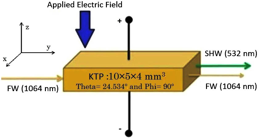
The dimension of the KTP crystal is assumed to be , as shown in Fig. 1. The RIs of the crystal along the principal axes are considered for the FWs as , , and and for the SHW as , , and [21]. Superscripts 1 and 2 denote FW and SHW, respectively. , , and are the principal axes of the KTP crystal. The electro-optic coefficients of the KTP crystal are , , and [15].
Figure 1.Application of electric field along the -axis, and the propagation of FW along the plane of the KTP crystal.
The FWs of the incident beam are propagated along the type II phase-matching direction of the crystal, making angles of and when there is no applied voltage to the crystal. The beam waist is assumed to be 80 μm, for a total intensity of . Hence, the diffraction length of the beam must be greater than the crystal length of the fundamental beam waist of 80 μm. The direction of propagation of FWs of 1064 nm for type II critical phase matching is on plane of the bulk KTP crystal at room temperature (30°C). When a calculated DC electric field of is applied to the bulk KTP crystal, the index ellipsoid and the principal RIs of the crystal will be modified, and the phase-mismatch condition will occur within the propagating FWs in the type II phase-matching direction. This applied electric field along crystal’s thickness of 4 mm can be converted to applied voltage by the equation of i.e. 8 kV, where is the thickness of the crystal, is the applied voltage, and denotes the applied electric field. By tuning the applied voltage to the crystal, can also be tuned along the propagation length (), as shown in Fig. 2. The maximum is calculated as 7.86 radians for an applied voltage of .
Figure 2.Change of with respect to the applied voltage.
From Fig. 2, it is seen that and its sign can easily be changed by changing the strength and polarity of the applied voltage, which is important in cascaded nonlinearity for self-focusing and defocusing FWs.
When a beam interacts with a nonlinear crystal, it does not focus, as there is no phase shift in the FWs of the incident beam. After several repetitions of upconversion (FW to SH) and downconversion (SH to FW), the required nonlinear phase shift is attained by the FWs. For focusing a beam, sufficient nonlinear phase shifts of the FWs are required inside the crystal. These nonlinear phase shifts propagating along the type II phase-matching direction inside the crystal after applying voltage can be calculated numerically, as shown in Fig. 3.
Figure 3.Nonlinear phase of the FW along the propagation length for (a) and (b) .
Figure 3 shows the variations of the nonlinear phase shifts of the FWs with respect to (w.r.t.) the propagation distance according to different applied voltages at two different peak intensities. At zero applied voltage, is zero along the propagation distance, as shown by sky-blue solid line in Figs. 3(a) and 3(b) at both intensities viz. 0.2 and , respectively. When the applied voltage changes (namely 2, 5, or 7 kV), of the FWs also changes at different intensities, as shown by green, pink, and blue solid lines in Fig. 3. Here, it is seen that the variation of at is higher than at . Hence we can say that at higher intensity, will be greater. The increase in the interaction of the unconverted and reconverted FWs may introduce a much higher nonlinear within the FWs, which can be controlled by controlling the applied voltage. However, and , due to , can also be controlled by controlling the voltage applied to the crystal, as shown in Fig. 4.
Figure 4.Change of and w.r.t. the applied voltage.
In Fig. 4, it is clearly seen that, at zero applied voltage, and are also zero. By tuning the applied voltage from 0 to , and can also be controlled from the minimum to the maximum level, as shown by regions A (0 to kV) and B (0 to 8 kV) in Fig. 4, which describe the focusing and defocusing conditions of the incident beam, respectively. The maximum calculated to be 1.44 radians. The maximum due to is calculated to be , which is one order higher than the other methods reported to date. The focusing–defocusing of the FWs by applying voltage helps to design a tunable lens within the crystal, whereas the focal length of the lens depends on and , which can also be controlled by controlling , as shown in Fig. 5.
Figure 5 shows the changes of and with the change of , where the regions around C (negative values of ) and D (positive values of ) are responsible for focusing and defocusing the beam, respectively, which introduces the behavior of a lens within the crystal. From Fig. 5, it is clearly understood that when is zero, and are also zero. By changing , it is possible to tune and , as shown in Fig. 5. Thus, the focal length of this lens is dependent on and , which can be tuned by controlling the applied voltage, as shown in Fig. 6.
Figure 6.Change of the focal length of the cascaded Kerr lens w.r.t. the applied voltage.
Figure 6 shows the variation of the focal length of the cascaded Kerr lens with the varying applied voltages, where the regions around E (0 to ) and F (0 to 8 kV) are showing the condition of positive and negative lenses, respectively. At zero applied voltage, the focal length of the cascaded Kerr lens is zero. By tuning the applied voltage from 0 to kV, maximum tuning of the focal length for positive and negative lenses is calculated. The minimum and maximum focal lengths are calculated as and for an applied voltages of and kV, respectively.
In conclusion, we analytically demonstrate an electro-optically tunable cascaded Kerr lens in a bulk KTP crystal. A voltage of is calculated to apply on an plane of a 1 cm long crystal having a thickness of 4 mm to create a of radians, which transforms the second-order nonlinearity into cascaded nonlinearity. The sign of this can be easily changed by changing the polarity of the voltage applied to the crystal. due to within the propagating FWs creates the cascaded nonlinearity, analogous to Kerr nonlinearity. An analogy has been made by comparing within FWs, resulting in a comparison of cascaded nonlinearity with Kerr nonlinearity. The value of , responsible for the focusing and defocusing effects in cascaded Kerr-like nonlinearity achieved through the cascaded process, can be calculated numerically. The values of and can be varied by varying the voltage applied to the crystal. The nonuniform radial distribution of the incident Gaussian beam curves the fundamental wavefront, which focuses and defocuses while propagating through the crystal. Depending on the polarity of the applied voltage, the medium acts as a positive or negative lens having an intensity-dependent focal length. The minimum calculated focal length of the positive lens is 3.68 mm for an applied voltage of 0.3 kV for a peak beam intensity of having a beam waist 80 μm in a bulk KTP crystal. The maximum value of is achieved at .
The benefit of this method is that the bulk KTP itself behaves like a configurable lens, which is much easier to control by tuning the electric field applied to the crystal. Therefore, controlling the focal length the cascaded Kerr lens will be more accurate when the cavity loss is less and mode locking is easier. Hence, this method can be applied to Kerr-lens mode locking of the laser cavity for the generation of picosecond pulses by controlling the focal length of an electro-optically tunable cascaded Kerr lens. Furthermore, in electro-optic tuning, no losses occur within the cavity, as there is no requirement for an extra setup and no change in the incident angle of the fundamental beam. Unlike angle tuning, there is no scope of misalignment, as the crystal acts as a configurable lens of the required focal length. For the adaptive optical requirement, this method can also be utilized to compensate for the effect of thermal lensing of the gain medium at a high pump power level.
Ruma Debnath, Digvijay Singh Hada, Susheel Kumar Beda, Ardhendu Saha. Electro-optically tunable self-focusing and self-defocusing in KTP crystals by a cascaded second-order process[J]. Chinese Optics Letters, 2016, 14(12): 121902