Fuchuan Lei, Rafino M. J. Murphy, Jonathan M. Ward, Yong Yang, and Síle Nic Chormaic*
Abstract
Tapered fibers with diameters ranging from 1 to 4 μm are widely used to excite the whispering-gallery (WG) modes of microcavities. Typically, the transmission spectrum of a WG cavity coupled to a waveguide around a resonance assumes a Lorentzian dip morphology due to resonant absorption of the light within the cavity. In this paper, we demonstrate that the transmission spectra of a WG cavity coupled with an ultrathin fiber (500–700 nm) may exhibit both Lorentzian dips and peaks, depending on the gap between the fiber and the microcavity. By considering the large scattering loss of off-resonant light from the fiber within the coupling region, this phenomenon can be attributed to partially resonant light bypassing the lossy scattering region via WG modes, allowing it to be coupled both to and from the cavity, then manifesting as Lorentzian peaks within the transmission spectra. This implies the system could be implemented within a bandpass filter framework.1. INTRODUCTION
In recent years, whispering-gallery (WG) mode microcavities have attracted considerable interest for both fundamental research and applications [1–10]. The main advantages of WG cavities are their ultrahigh quality () factors and small mode volumes, inherent attributes that allow for the effective trapping of light, both spatially and temporally. Consequently, the use of WG resonators makes it possible to significantly enhance light–matter interactions. As a result, they have been used to study strong coupling between a single atom and a cavity mode [11], ultralow threshold Raman lasing [12], parametric oscillation [13,14], frequency comb generation [15–17], and optomechanical effects [18–22], etc. During studies of this nature, it is imperative that light is coupled in and out of the microcavity with high efficiency. Among the various coupling schemes, the tapered fiber-side coupling technique stands out from the rest. It is predominantly used due to its inherent ultralow loss and easy manipulation [23], especially for silica microcavities.
Unlike the Fabry–Perot cavity, the typical transmission spectrum of the WG microcavity side-coupled to a waveguide exhibits a Lorentzian dip around a resonant frequency. The transmitted light is a superposition of two components: one directly passing through the waveguide and another coming from the cavity. A phase difference between these two components results in destructive interference [24]. These Lorentzian dips have been explored for use in narrow band-stop filters. However, to realize the bandpass function, an add-drop configuration is needed [10,25], requiring the inclusion of additional coupling devices. In this paper, we observe that the transmission spectra of a WG cavity side-coupled to a single tapered fiber may exhibit Lorentzian peak behavior when the diameter of the tapered fiber is smaller () than conventional values (). Considering that the scattering loss due to the thinner tapered fiber is large when a microcavity is in close proximity to it, we can attribute the phenomenon to partially resonant light bypassing the strong scattering region mediated by cavity modes, while off-resonant light experiences significant scattering, resulting in appreciable transmission loss.
2. EXPERIMENTAL METHOD
A schematic of the experimental setup is shown in Fig. 1. The WG microcavities in our experiment were fixed-stem, silica microspheres with diameters ranging from 40 to 150 μm, fabricated from single-mode fiber (SMF-28, Thorlabs). Silica microspheres were made in the standard manner using a focused laser beam (power ) directed onto a section of silica single-mode optical fiber. A small weight attached to the bottom of the fiber upon heating ensured the formation of a tapered region, which acts as the stem of the microsphere. The laser was then used to cut the fiber and the remaining glass at the tip was reheated. Surface tension of the molten silica caused the tip to assume a spherical morphology. Finally, further broad-focus laser heating of the microsphere was conducted to reduce surface irregularities.
Sign up for Photonics Research TOC. Get the latest issue of Photonics Research delivered right to you!Sign up now
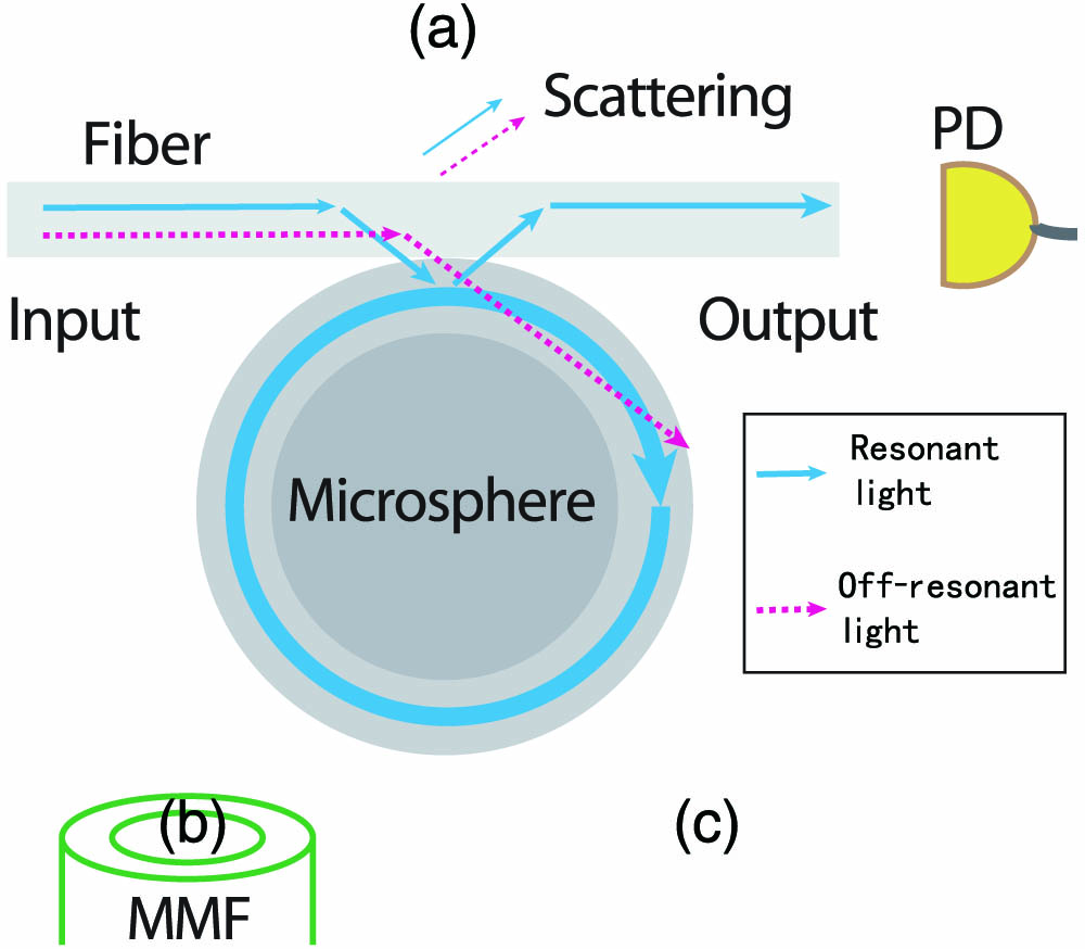
Figure 1.Schematic of the experimental setup. A tapered fiber is side-coupled to a microsphere for transmission spectra measurements. Aside from direct monitoring of the transmitted light by a PD, an MMF is mounted at different positions (a), (b), (c) to collect the scattered light from the tapered fiber-microsphere coupled system. The blue solid line and the red dashed line represent the resonant light and off-resonant light, respectively.
The tapered fiber used for light coupling was fabricated by heating a strand of SMF-28 with a ceramic heater (CMH-7-19, NTT-AT) and simultaneously stretching it. In this work, the waist diameter of the tapered fiber used was 500–700 nm, and was measured by scanning electron microscopy (SEM). Light from a tunable 1550 nm laser (TLB-6728, New Focus) was sent through one end of the taper to couple both in and out of the WG microsphere. The transmitted light was detected on a photodetector (PD, PDA10CF-EC, Thorlabs). Aside from the PD, a multimode fiber (MMF), with a diameter of 125 μm and a core diameter of 62.5 μm, was mounted near the system in the equatorial plane perpendicular to the stem of the sphere. The MMF was used to collect the scattered light and was connected to another PD, which is not shown in Fig. 1.
3. RESULTS AND DISCUSSION
Figure 2(a) shows the evolution of the transmission spectrum as the tapered fiber-microsphere gap was altered. From A to H, the gap decreased from 2.4 to 0 μm (i.e., in contact). While the gap was decreased gradually (), more and more WG modes were excited. However, some Lorentzian dips disappeared and some Lorentzian peaks emerged as the gap was decremented further (). At the same time, the normalized transmittance of the off-resonant light decreased from unity to nearly zero, as shown in Fig. 2(b). This indicates that scattering loss due to the microsphere’s close proximity to the nanofiber was no longer negligible in contrast to that seen in previous reports (less than 5%) [26]—especially when the gap between the two approaches zero. Since the tapered nanofiber diameter was of sub-wavelength dimensions, the fiber mode possessed an evanescent component that extended significantly into the free space surrounding the tapered region [see Fig. 3(c)]; e.g., the evanescent field of the mode at 1550 nm band can extend about 3 μm from the surface for a 600 nm diameter fiber. As shown in Fig. 2(a), almost all (97%) the off-resonant light was lost when the microsphere was in contact with the ultrathin fiber, while a reduced amount of the resonant light survived (more than 20%). It is worth noting that the linewidth of one particular peak is less than 10 MHz (indicative of a high- factor of ) even while the resonator is in contact with the ultrathin fiber.

Figure 2.(a) Normalized transmission spectra and (b) the corresponding transmittance of off-resonant light, for varying taper-microsphere gaps. From A to H, the gap decreases from 2.4 μm to 0. For both (a) and (b), the axis corresponds to transmittance, which has been normalized with respect to the maximum value observed in the transmission spectrum A.
Figure 3.(a) Transmission spectra and (b) the corresponding transmittance of off-resonant light with varying input polarization direction. From A to E, the polarization direction changes by 90°. The polarization was incremented in steps of 10° for a net change of 400°. (c) The simulated electric field distribution of the linearly polarized, mode for a fiber with a diameter of 600 nm. The arrows indicate the direction of the electric field along the cross-section.
Figure 3(a) depicts a series of transmission spectra for varying linear polarization orientations. The direction of polarization was altered by rotating a half-wave plate prior to the linearly polarized light coupling into the ultrathin fiber. Though it is evident that the transmission spectra change with the direction of polarization, many modes still retain their Lorentzian peak morphology. Also note that the transmittance of the off-resonant light varies sinusoidally with the input polarization, as shown in Fig. 3(b). Considering that the ultrathin fiber can only support the fundamental fiber-guided mode, , and its field distribution is determined by the polarization of the input light [27], as shown in Fig. 3(c), it follows by extension that the scattering strength should be polarization dependent.
Figure 4 shows a series of contact-coupling transmission spectra for tapered fibers of varying thickness. From bottom to top, the fiber diameter is increased from 600 nm to about 3 μm. As the fiber diameter increases, the spatial extent of the surrounding evanescent field diminishes, resulting in a decrease in scattering losses and the transmission of off-resonance light increases from nearly zero to unity. Consequently, as the fiber diameter is increased the Lorentzian peaks disappear, and the characteristic resonance Lorentzian dips are reinstated.
Figure 4.Transmission spectra for contact coupling with different fiber diameters. From bottom to top, the tapered fiber was translated to increase its diameter at the coupling point. According to the displacement, the diameter was estimated to be 600 nm, 800 nm, 1.2 μm, 1.7 μm, and 3 μm, respectively.
To better illustrate the scattering loss and how it manifests in the transmission spectra, we performed finite element method (FEM) numerical simulations using COMSOL, and the results are given in Fig. 5. As a proof-of-principle, a two-dimensional (2D) model was constructed for simplicity. The thickness of the waveguide used in simulations was 400 nm with a refractive index of 1.35, thereby providing an effective index of 1.125 for the propagating mode. In the actual experiment, the refractive index of the circular tapered fiber is 1.45 with an effective mode index of 1.025 (from simulation). Since the 2D simulation uses a planar waveguide to simulate a waveguide with a similar effective index as the tapered fiber, the waveguide’s index must be set to less than 1.45; otherwise its size would be too small. The microsphere is simplified using a microring cavity model with a refractive index of 1.45, a thickness of 10 μm, and outer diameter of 40 μm. The calculated transmission spectrum, from 1524.8 to 1528.7 nm, is shown in Fig. 5(a). Similar to the observed spectra [e.g., see the bottom of Fig. 2(a)], there is a peak at 1526.5 nm, which corresponds to a second-order radial mode. The slight asymmetry in the mode profile can be attributed to interference with the fundamental mode, which has a lower factor due to contact with the waveguide. The electric field distribution perpendicular to the taper of the aforementioned mode is shown in Fig. 5(b), while Fig. 5(c) corresponds to the off-resonant light case (1525.9 nm).
Figure 5.FEM simulation results. (a) Transmission spectrum: The distribution of the electrical field for (b) resonant case and (c) off-resonant case.
From the calculated field distribution in Figs. 5(b) and 5(c), the scattering caused by the sphere can be explained as follows. The effective mode index of the fiber taper, which is 1.025 as previously mentioned, is quite small compared to that of the microsphere since its diameter is far less than the operating wavelength. Though phase mismatching exists between the fiber mode and the cavity modes, the light is still almost completely refracted into the sphere if the fiber is close to it. As a result, it no longer propagates directly along the fiber. Nevertheless, the light can be partially coupled back to the fiber if it is resonant with a cavity mode. This can happen because the resonant light can have a very high intensity and circulate along the periphery of the sphere (confined by total internal reflection). Conversely, the off-resonant light will leak out from the cavity in all directions (see Fig. 1), which results in no strong field build-up, thus decreasing the amount of light that can be coupled back into the fiber.
To confirm our hypothesis, the optical field distribution of the coupling system was monitored by introducing an MMF to collect the scattered light. The MMF was placed at positions (a), (b), and (c) (see Fig. 1), and the transmission spectrum at each location was recorded, as shown in Fig. 6 (blue, upper curves). For ease of comparison, both the spectra of the fiber taper output (red, lower curves) and the MMF transmission spectra are plotted together, none of which have been normalized, but whose transmission values have been shifted relative to each other. For this experiment, an erbium-doped fiber amplifier (EDFA) was used to amplify the input signal to augment the scattered signal strength. EDFA power fluctuations resulted in the non-flat transmission baseline evident in Fig. 6. When the MMF was located at positions (a) and (c), both strong scattering signals and numerous dips in the scattered spectra were observed. This result implies that the collected off-resonant scattered light dominates over the resonant light, which was confined in the cavity and coupled out to the ultrathin fiber. At position (b), only resonant light losses were collected by the MMF, resulting in the peaks evident in the spectrum. Also note that there are some peaks in the transmission spectra that have no corresponding peaks in the scattered spectra, which may be due to the low collection efficiency of the MMF and the relatively weak scattering strength from low modes. This result leads us to the conclusion that the amount of scattered off-resonant light is much weaker at position (b) than at positions (a) and (c). By extension, it also demonstrates that some WG modes are excited by the ultrathin fiber. It should be noted that some peaks in the ultrathin fiber transmission spectra coincide with some of the peaks observed in the MMF spectrum, indicating that those peaks are indeed from resonant light within the cavity modes. In fiber-coupled WG microcavity systems, there may be several other mechanisms based on mode interference that lead to the peak formation in the transmission spectra, such as electromagnetically induced transparency [28] and Fano resonances [29–34]. However, the aforementioned mechanisms do not explain the simultaneous occurrence of peaks in both the ultrathin fiber and MMF spectra.
Figure 6.Spectra of the transmission through the ultrathin fiber (red, bottom) and the scattering spectra from the multimode fiber (blue, top). For ease of comparison, the spectra are not normalized but shifted relative to each other. (a), (b), and (c) correspond to the multimode fiber being placed at positions (a), (b), and (c) in Fig. 1.
4. SUMMARY
In summary, we have studied the transmission spectra of WG microcavities with respect to tapered ultrathin fiber coupling systems. Within this coupling framework, the off-resonant scattering losses from the narrow tapered fiber region while in close proximity to the microsphere have been found to be significant, and they play a crucial role in the formation of the Lorentzian peaks observed in the transmission spectra. The existence of these Lorentzian peaks in the experimental results suggest that the system, in principle, could be used as a bandpass filter. Additionally, this work offers an alternative means to control the behavior of transmission spectra by manipulating the amount of scattering loss. This ability may be useful when striving for high experimental precision and may have advantages for sensing applications.
Acknowledgment
Acknowledgment. The authors wish to thank J. Du for measuring the fiber diameters.
References
[1] V. S. Ilchenko, A. B. Matsko. Optical resonators with whispering-gallery modes-part II: applications. IEEE J. Sel. Top. Quantum Electron., 12, 15-32(2006).
[2] B. Peng, S. K. Özdemir, F. Lei, F. Monifi, M. Gianfreda, G. L. Long, S. Fan, F. Nori, C. M. Bender, L. Yang. Parity-time-symmetric whispering-gallery microcavities. Nat. Phys., 10, 394-398(2014).
[3] Y. Yang, S. Saurabh, J. M. Ward, S. Nic Chormaic. High-Q, ultrathin-walled microbubble resonator for aerostatic pressure sensing. Opt. Express, 24, 294-299(2016).
[4] M. Sumetsky. Whispering-gallery-bottle microcavities: the three-dimensional etalon. Opt. Lett., 29, 8-10(2004).
[5] J. M. Ward, Y. Wu, V. G. Vladimir, S. Nic Chormaic. Trapping of a microsphere pendulum resonator in an optical potential. Phys. Rev. A, 79, 053839(2009).
[6] B. Peng, S. K. Özdemir, M. Liertzer, W. Chen, J. Kramer, H. Yılmaz, J. Wiersig, S. Rotter, L. Yang. Chiral modes and directional lasing at exceptional points. Proc. Natl. Acad. Sci. USA, 113, 6845-6850(2016).
[7] X. Jiang, C. Yang, H. Wu, S. Hua, L. Chang, Y. Ding, Q. Hua, M. Xiao. On-chip optical nonreciprocity using an active microcavity. Sci. Rep., 6, 38972(2016).
[8] Y. Yang, F. Lei, S. Kasumie, L. Xu, J. Ward, L. Yang, S. Nic Chormaic. Tunable erbium-doped microbubble laser fabricated by sol-gel coating. Opt. Express, 25, 1308-1313(2017).
[9] J. M. Ward, Y. Yang, S. Nic Chormaic. Glass-on-glass fabrication of bottle-shaped tunable microlasers and their applications. Sci. Rep., 6, 25152(2016).
[10] P. Wang, R. Madugani, H. Zhao, W. Yang, J. M. Ward, Y. Yang, G. Farrell, G. Brambilla, S. Nic Chormaic. Packaged optical add-drop filter based on an optical microfiber coupler and a microsphere. IEEE Photon. Technol. Lett., 28, 2277-2280(2016).
[11] T. Aoki, B. Dayan, E. Wilcut, W. P. Bowen, A. S. Parkins, T. J. Kippenberg, K. J. Vahala, H. J. Kimble. Observation of strong coupling between one atom and a monolithic microresonator. Nature, 443, 671-674(2006).
[12] S. M. Spillane, T. J. Kippenberg, K. J. Vahala. Ultralow-threshold Raman laser using a spherical dielectric microcavity. Nature, 415, 621-623(2002).
[13] T. J. Kippenberg, S. M. Spillane, K. J. Vahala. Kerr-nonlinearity optical parametric oscillation in an ultrahigh-Q toroid microcavity. Phys. Rev. Lett., 93, 083904(2004).
[14] D. Farnesi, A. Barucci, G. C. Righini, S. Berneschi, S. Soria, G. Nunzi Conti. Optical frequency conversion in silica-whispering-gallery-mode microspherical resonators. Phys. Rev. Lett., 112, 093901(2014).
[15] Y. Yang, X. Jiang, S. Kasumie, G. Zhao, L. Xu, J. M. Ward, L. Yang, S. Nic Chormaic. Four-wave mixing parametric oscillation and frequency comb generation at visible wavelengths in a silica microbubble resonator. Opt. Lett., 41, 5266-5269(2016).
[16] P. DelHaye, A. Schliesser, O. Arcizet, T. Wilken, R. Holzwarth, T. J. Kippenberg. Optical frequency comb generation from a monolithic microresonator. Nature, 450, 1214-1217(2007).
[17] T. Kato, A. Hori, R. Suzuki, S. Fujii, T. Kobatake, T. Tanabe. Transverse mode interaction via stimulated Raman scattering comb in a silica microcavity. Opt. Express, 25, 857-866(2017).
[18] M. Aspelmeyer, T. J. Kippenberg, F. Marquardt. Cavity optomechanics. Rev. Mod. Phys., 86, 1391-1452(2014).
[19] R. Madugani, Y. Yang, J. M. Ward, V. H. Le, S. Nic Chormaic. Optomechanical transduction and characterization of a silica microsphere pendulum via evanescent light. Appl. Phys. Lett., 106, 241101(2015).
[20] F. Monifi, J. Zhang, S. K. Özdemir, B. Peng, Y.-X. Liu, B. Fang, F. Nori, L. Yang. Optomechanically induced stochastic resonance and chaos transfer between optical fields. Nat. Photonics, 10, 399-405(2016).
[21] F.-C. Lei, M. Gao, C. Du, Q.-L. Jing, G.-L. Long. Three-pathway electromagnetically induced transparency in coupled-cavity optomechanical system. Opt. Express, 23, 11508-11517(2015).
[22] M. Asano, Y. Takeuchi, W. Chen, S. K. Özdemir, R. Ikuta, N. Imoto, L. Yang, T. Yamamoto. Observation of optomechanical coupling in a microbottle resonator. Laser Photon. Rev., 10, 603-611(2016).
[23] J. C. Knight, G. Cheung, F. Jacques, T. A. Birks. Phase-matched excitation of whispering-gallery-mode resonances by a fiber taper. Opt. Lett., 22, 1129-1131(1997).
[24] H. A. Haus. Waves and Fields in Optoelectronics(1984).
[25] H. Rokhsari, K. J. Vahala. Ultralow loss, high Q, four port resonant couplers for quantum optics and photonics. Phys. Rev. Lett., 92, 253905(2004).
[26] M. Cai, O. Painter, K. J. Vahala. Observation of critical coupling in a fiber taper to a silica-microsphere whispering-gallery mode system. Phys. Rev. Lett., 85, 74-77(2000).
[27] L. Tong, M. Sumetsky. Subwavelength and Nanometer Diameter Optical Fibers(2011).
[28] Y. Yang, S. Saurabh, J. Ward, S. Nic Chormaic. Coupled-mode-induced transparency in aerostatically tuned microbubble whispering-gallery resonators. Opt. Lett., 40, 1834-1837(2015).
[29] A. Chiba, H. Fujiwara, J. Hotta, S. Takeuchi, K. Sasaki. Fano resonance in a multimode tapered fiber coupled with a microspherical cavity. Appl. Phys. Lett., 86, 261106(2005).
[30] B.-B. Li, Y.-F. Xiao, C.-L. Zou, Y.-C. Liu, X.-F. Jiang, Y.-L. Chen, Y. Li, Q. Gong. Experimental observation of Fano resonance in a single whispering-gallery microresonator. Appl. Phys. Lett., 98, 021116(2011).
[31] F. Lei, B. Peng, S. K. Özdemir, G. L. Long, L. Yang. Dynamic Fano-like resonances in erbium-doped whispering-gallery-mode microresonators. Appl. Phys. Lett., 105, 101112(2014).
[32] Y. Miao, Y. Peng, Y. Xiang, M. Li, Y. Lu, Y. Song. Dynamic Fano resonance in thin fiber taper coupled cylindrical microcavity. IEEE Photon. J., 8, 1-6(2016).
[33] Y.-L. Shang, M.-Y. Ye, X.-M. Lin. Experimental observation of Fano-like resonance in a whispering-gallery-mode microresonator in aqueous environment. Photon. Res., 5, 119-123(2017).
[34] G. Zhao, S. K. Özdemir, T. Wang, L. Xu, E. King, G. L. Long, L. Yang. Raman lasing and Fano lineshapes in a packaged fiber-coupled whispering-gallery-mode microresonator. Sci. Bull., 62, 875-878(2017).


