
Zhenhua Feng, Honglin Ji, Ming Tang, Lilin Yi, Lin Gan, Lei Xue, Qiong Wu, Borui Li, Jiajia Zhao, Weijun Tong, Songnian Fu, Deming Liu, Weisheng Hu. C-band real-time 400/300 Gb/s OOK bidirectional interconnection over 20 km multicore fibers[J]. Chinese Optics Letters, 2017, 15(8): 080602
- Chinese Optics Letters
- Vol. 15, Issue 8, 080602 (2017)
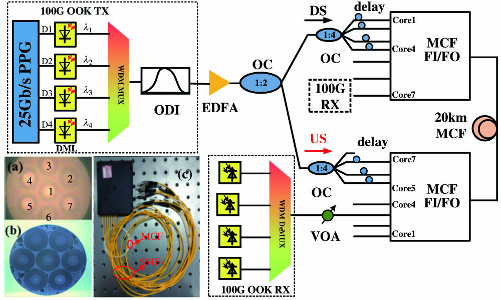
Fig. 1. Experimental setup of bidirectional MCF transmission system. The insets (a), (b), and (c) are the cross section view of the fabricated MCF, fan-in/fan-out, and picture of the whole fan-in/fan-out device, respectively. (OC, optical coupler; FI/FO, fan-in/fan-out; RX, receiver; Mux, multiplexer; DeMux, demultiplexer.)
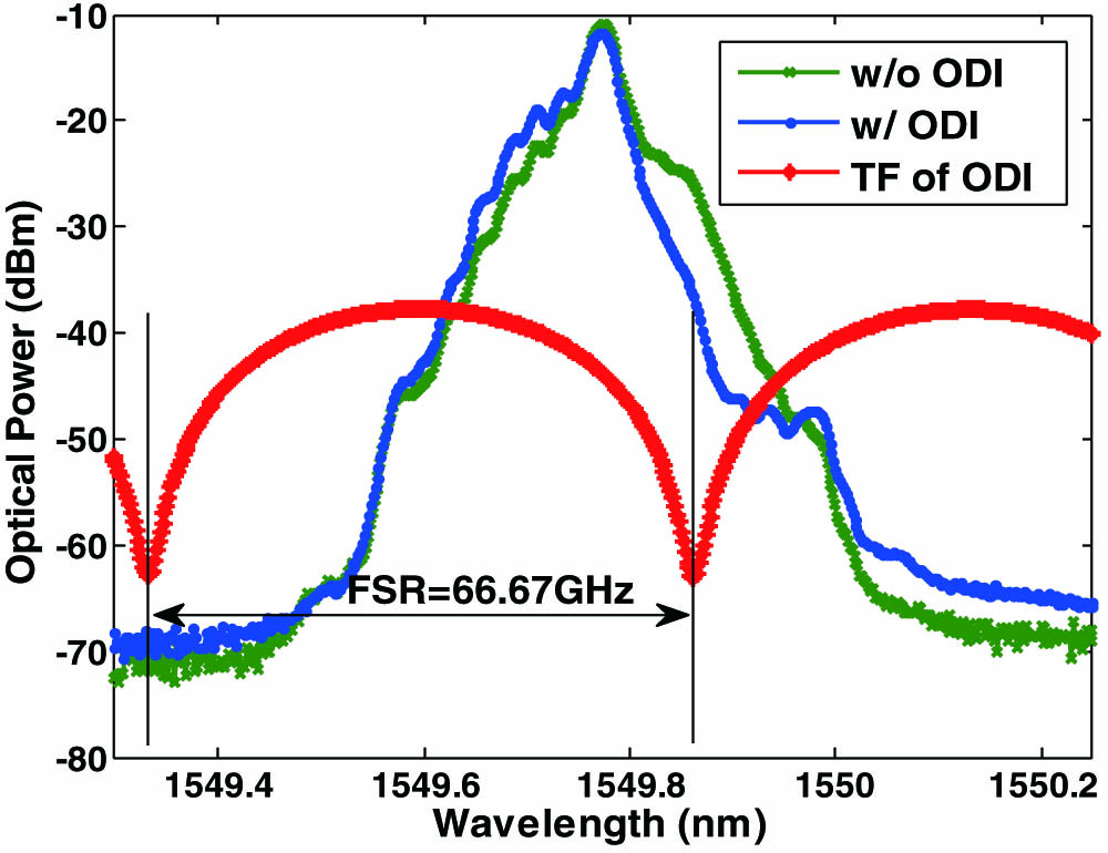
Fig. 2. (Color online) Spectrum of 25 Gb/s OOK signal generated by DML1 with and without ODI, the transmission function of the ODI is also depicted. (w/o, without; w/, with; TF, transmission function.)
Fig. 3. (Color online) Frequency response of the transceivers with and without ODI. (BW, bandwidth.)
Fig. 4. Optical spectra of the WDM multiplexed 100 Gb/s OOK signals after ODI filtering.
Fig. 5. Measured eye diagrams for the OB2B case with and without ODI. (a)
Fig. 6. Measured eye diagrams of 25G OOK signals after 20 km MCF transmission. (a)
Fig. 7. (Color online) BER performances of 100G OOK signals for different cores in bidirectional MCF transmission. (a)–(d) are for DS (core 1 and 2) and US (core 5 and 6), respectively. (
Fig. 8. Receiver sensitivity variation among different fiber cores and wavelengths. (

Set citation alerts for the article
Please enter your email address
© Copyright 2018-2021 | Chinese Laser Press. All Rights Reserved 沪ICP备15018463号-20