
Tianfu Yao, Liangjin Huang, Pu Zhou, Bing Lei, Jinyong Leng, Jinbao Chen. Power scaling on tellurite glass Raman fibre lasers for mid-infrared applications[J]. High Power Laser Science and Engineering, 2018, 6(2): 02000e24
- High Power Laser Science and Engineering
- Vol. 6, Issue 2, 02000e24 (2018)
![Raman gain coefficient of TBZN fibre pumped at 632.8 nm [30].](/richHtml/hpl/2018/6/2/02000e24/img_1.gif)
Fig. 1. Raman gain coefficient of TBZN fibre pumped at 632.8 nm [30].
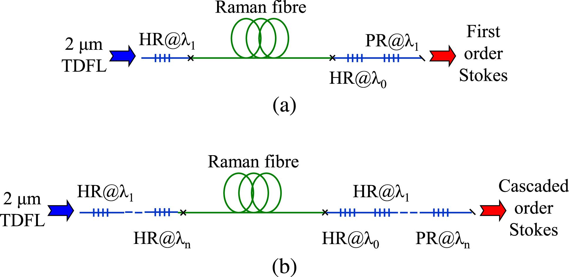
Fig. 2. The schematic of the all-fibrized (a) first-order and (b) cascaded RFLs. TDFL: Tm-doped fibre laser; HR: high reflectance; PR: partial reflectance.
Fig. 3. Calculated output power versus launched pump power for fluoride RFL in Ref. [20]. FDM: finite difference method.
Fig. 4. (a) Measured propagation loss spectrum of the TBZN fibre in Ref. [24]; (b) threshold power as a function of fibre length for output reflectance of 90%, 95% and 99%.
Fig. 5. Output power of the first-order RFL as a function of (a) output reflectance for fibre length of 0.3 m, 0.5 m, 1 m, 2 m, and (b) fibre length for output reflectance of 5%, 10%, 15% and 20%.
Fig. 6. (a) Power distribution along the fibre length in first-order RFL pumped by TDFL; (b) output power of first-order Stokes versus pump power.
Fig. 7. Power evolution of (a) pump, (b) first-order Stokes, (c) second-order Stokes waves in second-order RFL pumped by TDFL.
Fig. 8. Output power of second-order RFL as a function of (a) output reflectance for fibre length of 0.5 m, 1 m, 2 m and 3.1 m, (b) fibre length for output reflectance of 5%, 10%, 15% and 20%.
Fig. 9. Output power of second-order RFL under different pump powers.
Fig. 10. Longitudinal power evolution of (a) pump, (b) first-order Stokes, (c) second-order Stokes, (d) third-order Stokes in third-order RFL pumped by TDFL.
Fig. 11. Output power of third-order RFL as a function of (a) output reflectance for fibre length of 4.5 m, 5.5 m, 9 m and 11 m, (b) fibre length for output reflectance of 40%, 45%, 50% and 55%.
Fig. 12. Output power of third-order RFL as a function of pump power.

Set citation alerts for the article
Please enter your email address
© Copyright 2018-2021 | Chinese Laser Press. All Rights Reserved 沪ICP备15018463号-20