
Yu Bi, Lingling Huang, Tuo Li, Changhong Wang, Xiaofeng Zou, Lang Zhou, Guoguo Kang. Active metasurface via magnetic control for tri-channel polarization multiplexing holography[J]. Chinese Optics Letters, 2024, 22(4): 043601
- Chinese Optics Letters
- Vol. 22, Issue 4, 043601 (2024)
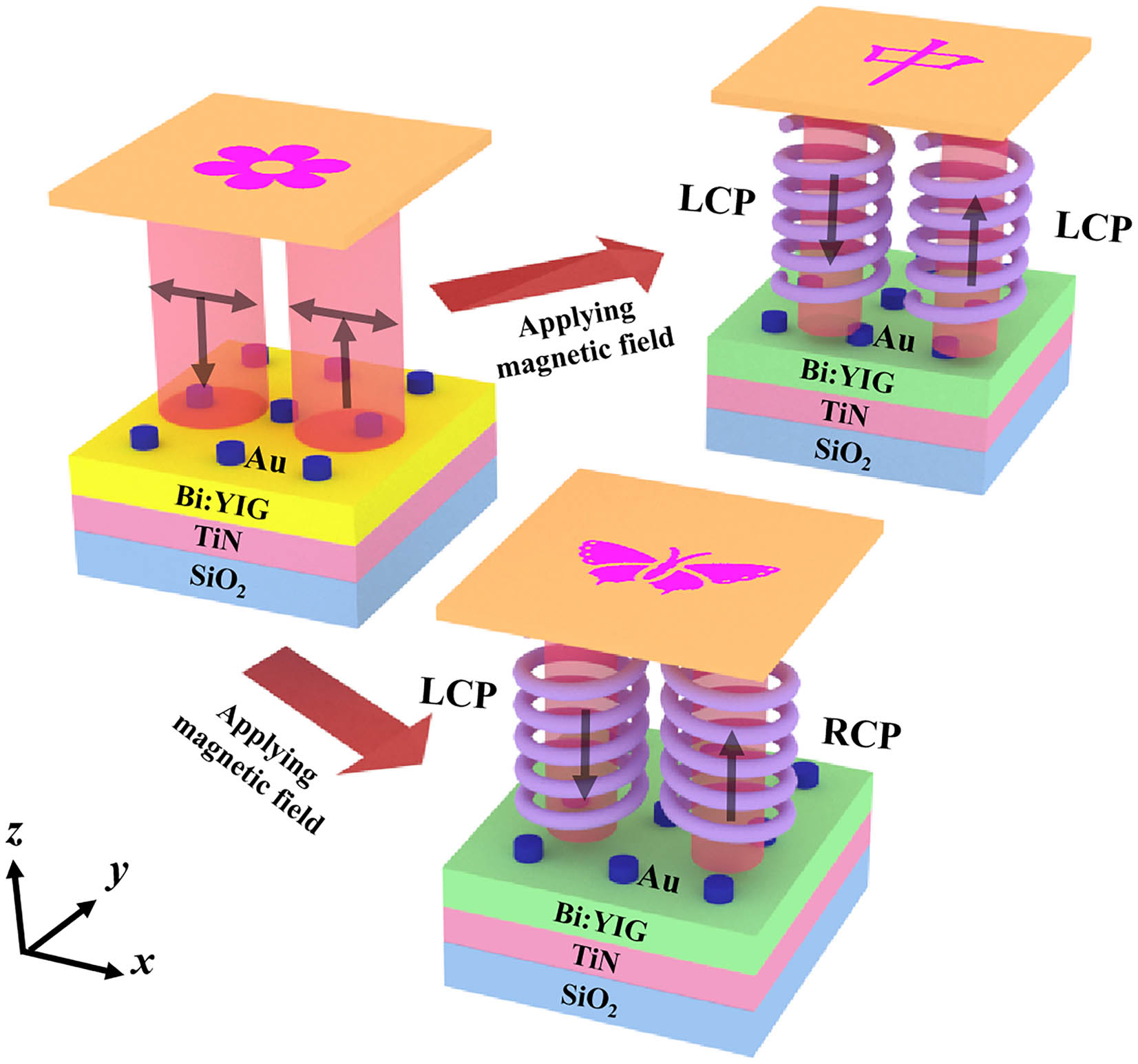
Fig. 1. Schematic of the magnetically controllable multichannel holographic display based on the MO metasurface.
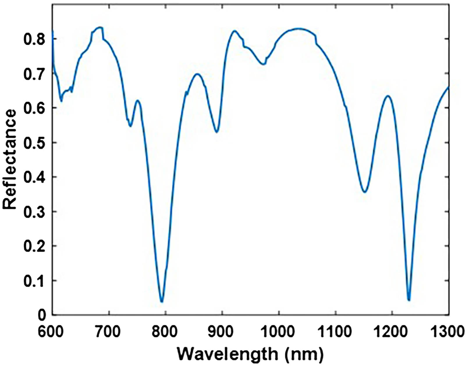
Fig. 2. Reflectance spectrum of the MO metasurface with the TM-polarized incident light.
Fig. 3. Calculated spatial distribution of (a) the electric and (b) the magnetic field for normally incident TM-polarized light. White lines denote the cross section of the structure.
Fig. 4. Complex amplitude modulation in the linear and circular polarization channels with the applied magnetic field. (a)–(d) Amplitude and phase modulation of the co- and cross-polarized reflected light with the x-polarized incident light. (e)–(h) Amplitude and phase modulation of the LCP and RCP reflected light with the LCP incident light.
Fig. 5. Complex amplitudes of the selected structures in the Exx, Ell, and Erl channels. The left axis demonstrates the amplitude distribution of the reflection light, with the pink/green/yellow bars representing the amplitude distribution in the Exx, Ell, and Erl channels, respectively. The right axis depicts the phase distribution of the reflection light, with the star/triangle/square representing the phase distribution in the Exx, Ell, and Erl channels, respectively.
Fig. 6. Schematic illustration of encoding multiple binary-amplitude holograms within one identical MO metasurface. The box represents each pixel unit. The boxes with different shaped markers represent the selected eight structures. The black and white boxes represent the amplitude modulation of 0 and 1 for the selected structure in different polarization channels. The black arrows indicate the input/output linearly and circularly polarized light.
Fig. 7. The multiple reconstructed holographic images within one identical MO metasurface in the different polarization channels. (a)–(c) Numerical reconstructions calculated by the modified GS algorithm. (d)–(f) Simulated reconstructions using full-wave calculations based on FDTD.
| ||||||||||||||||||||||||||||||||||||
Table 1. Geometric Parameters of the Selected Structures

Set citation alerts for the article
Please enter your email address
© Copyright 2018-2021 | Chinese Laser Press. All Rights Reserved 沪ICP备15018463号-20