• High Power Laser and Particle Beams
  • Vol. 35, Issue 3, 034004 (2023)
Wenzhong Zhou1、2、3, Weimin Pan1、3、*, Rui Ge1、3, Feisi He1, Zhongquan Li1, Zihan Wang1、3, Zhenghui Mi1, Tongming Huang1, jin Dai1, qiang Ma1, Miaofu Xu1, Mei Li1, Xiaolong Wang1、2, Baiqi Liu1, Xinying Zhang1, Huachang Liu1、2, Jun Peng1、2, and Sheng Wang1、2、3
Author Affiliations
  • 1Institute of High Energy Physics, Chinese Academy of Sciences, Beijing 100049, China
  • 2Spallation Neutron Source Science Center, Dongguan 523803, China
  • 3University of Chinese Academy of Sciences, Beijing 100049, China
  • show less
    DOI: 10.11884/HPLPB202335.220266 Cite this Article
    Wenzhong Zhou, Weimin Pan, Rui Ge, Feisi He, Zhongquan Li, Zihan Wang, Zhenghui Mi, Tongming Huang, jin Dai, qiang Ma, Miaofu Xu, Mei Li, Xiaolong Wang, Baiqi Liu, Xinying Zhang, Huachang Liu, Jun Peng, Sheng Wang. Design of the China Spallation Neutron Source phase II double spoke resonator[J]. High Power Laser and Particle Beams, 2023, 35(3): 034004 Copy Citation Text show less
    Schematic diagram of basic parameters of double-spoke cavity
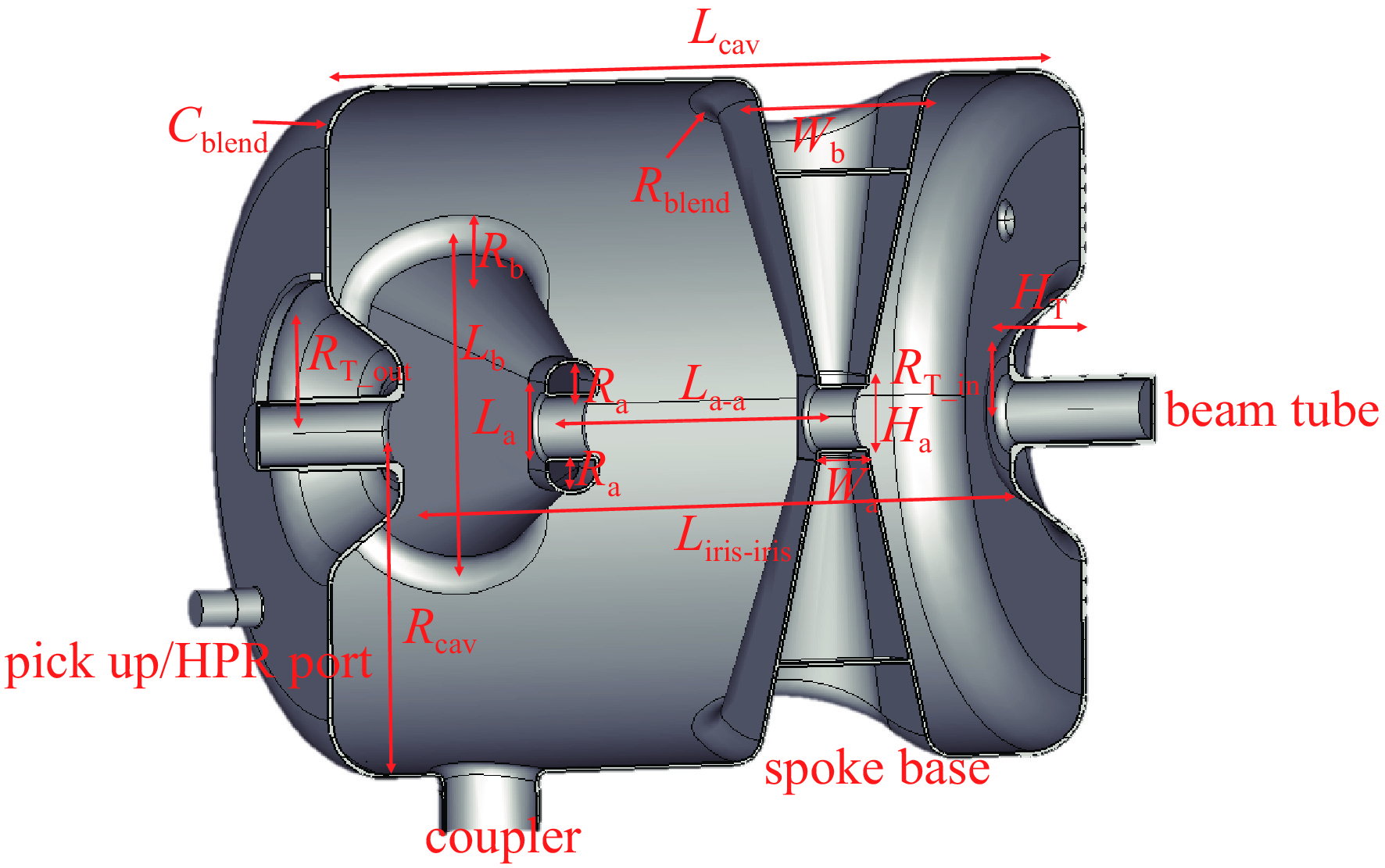
    Fig. 1. Schematic diagram of basic parameters of double-spoke cavity
    Flow chart of parameter optimization
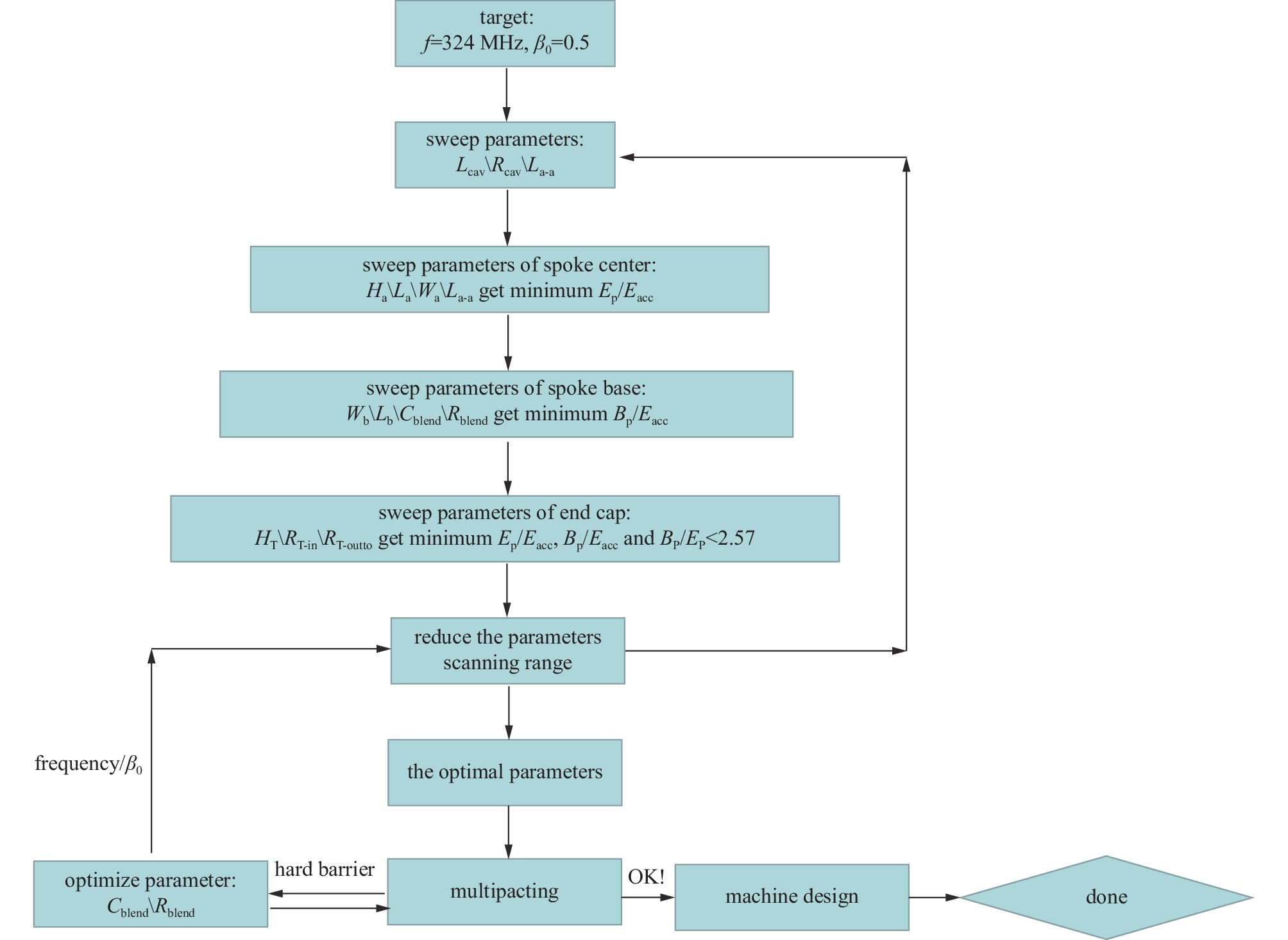
    Fig. 2. Flow chart of parameter optimization
    Distribution of electric field on the internal surface and axis withEp/Eacc =4.1
    Fig. 3. Distribution of electric field on the internal surface and axis withEp/Eacc =4.1
    TTF distribution of DSR
    Fig. 4. TTF distribution of DSR
    MP’s position and SEY simulation of different materials
    Fig. 5. MP’s position and SEY simulation of different materials
    Simulation calculation of coupler antenna and Qe
    Fig. 6. Simulation calculation of coupler antenna and Qe
    The mechanical structure of DSR
    Fig. 7. The mechanical structure of DSR
    Stress distribution of DSR and cambered reinforcing ribs
    Fig. 8. Stress distribution of DSR and cambered reinforcing ribs
    LFD coefficient of DSR
    Fig. 9. LFD coefficient of DSR
    Mechanical intrinsic frequency and vibration mode of DSR
    Fig. 10. Mechanical intrinsic frequency and vibration mode of DSR
    Decomposition of the earth magnetic field
    Fig. 11. Decomposition of the earth magnetic field
    Design of magnetic shield and distribution of residual magnetic field in axis of DSR
    Fig. 12. Design of magnetic shield and distribution of residual magnetic field in axis of DSR
    Welding diagram of DSR
    Fig. 13. Welding diagram of DSR
    frequency/MHzβ0aperture/mmEp/EaccBp/Eacc/(mT·MV−1·m) GR/Q)/Ω operating gradient/(MV·m−1)
    3240.5504.19.21204107.3
    Table 1. Main electromagnetic parameters of DSR
    modelfrequency/MHz
    1324
    2354
    3386
    4503
    5505
    6548
    7603
    8604
    9613
    10658
    Table 2. Fundamental model frequencies and high order mode frequencies of double spoke resonator (DSR)
    materialYoung’s modulus/GPayield strength/MPalimit strength/MPadensity/ (kg·m−3) Poisson’s ratio
    295 K4 K295 K4 K295 K4 K
    Ti106117275834344111745000.34
    Nb1051187069918574285600.39
    Nb55Ti626847647654554563660.34
    Table 3. Material parameters at different temperatures
    modelvibration modelvibration frequency/Hz
    1z-axis rotation 3.0
    2y-axis rotation 3.4
    3z-axis rotation 13.7
    4transverse vibration34.3
    5z-axis simultaneous vibration 167.6
    6z-axis anisotropic vibration 174.7
    7z-axis rotation 196.3
    Table 4. Vibration direction of each model
    Wenzhong Zhou, Weimin Pan, Rui Ge, Feisi He, Zhongquan Li, Zihan Wang, Zhenghui Mi, Tongming Huang, jin Dai, qiang Ma, Miaofu Xu, Mei Li, Xiaolong Wang, Baiqi Liu, Xinying Zhang, Huachang Liu, Jun Peng, Sheng Wang. Design of the China Spallation Neutron Source phase II double spoke resonator[J]. High Power Laser and Particle Beams, 2023, 35(3): 034004
    Download Citation