A signal processing method of realizing a large-range displacement measurement in a sinusoidal phase-modulating laser diode interferometer is proposed. The method of obtaining the dynamic value of the effective sinusoidal phase-modulating depth is detailed, and the residual amplitude modulation is also taken into account. Numerical simulations and experiments are carried out to compare this method with the traditional one. We prove that, with this method, the sinusoidal phase-modulating laser diode interferometer can realize a centimeter-level displacement measurement range with high precision, which is much better than the traditional method.
The sinusoidal phase-modulating laser diode (SPM-LD) interferometer has been used for vibration sensing and displacement measurement because of unique features such as simplicity and good expansibility[1–17]. However, the measurement range of this interferometer is limited to a few micrometers because an important parameter, the effective SPM depth, is considered to be a constant in conventional signal processing[1–3]. The effective SPM depth actually is linear to the length difference between the reference arm and the measurement arm in the SPM-LD interferometer[4,5]. As a result, the traditional method would result in great errors in the large-range displacement measurement. Therefore, to realize the large-range displacement measurement accurately, special methods are required to get the dynamic value of the effective SPM depth. Some patents set the effective SPM depth as a small number and apply the equivalent infinitesimal replacement method to estimate its dynamic value[6–9]. This is very useful, but because of the small number set as the effective SPM depth, the amplitudes of the harmonics extracted from the interference signal could be very small, which would give a low signal-to-noise ratio (SNR) and limit the entire measurement accuracy. In addition, the sinusoidal modulation of the frequency involves a residual amplitude modulation (RAM) to the laser, which would also cause errors and need to be taken into account[10,11].
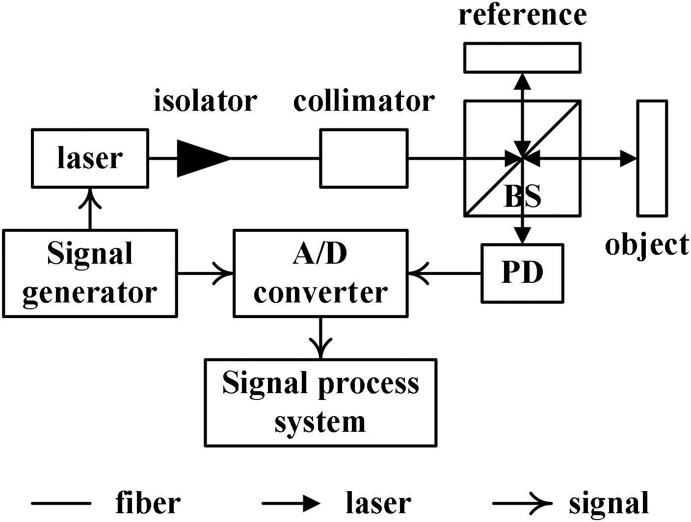
Figure 1.Structure of the SPM-LD interferometer for the large-range displacement measurement.
In this Letter, a novel signal processing method is proposed to improve the performance of a large-range displacement measurement in the SPM-LD interferometer by obtaining the dynamic value of the effective SPM depth. Numerical simulations and experiments are carried out to compare the novel method with the traditional one. The simulation and experimental results prove that the displacement measurement range of the SPM-LD interferometer can be enlarged to the centimeter level with high precision.
Figure 1 shows the structure of the SPM-LD interferometer for the large-range displacement measurement.
Sign up for Chinese Optics Letters TOC. Get the latest issue of Chinese Optics Letters delivered right to you!Sign up now
The light from the laser, whose frequency is modulated by the SPM signal from the signal generator, is emitted by the collimator after it goes through the isolator. The frequency modulation of the laser leads to a phase modulation term in the interference signal[4,5]. The laser is split into two parts by the beam splitter (BS). One part, which is reflected by the reference mirror, serves as a reference wave. The other part, which is reflected by the object mirror, serves as a measurement wave. The reference wave and measurement wave are recombined by the BS and interfere with each other. And, the interference signal is detected by the photoelectric detector (PD) and acquired by the A/D converter. The SPM signal, which is generated by the signal generator and modulates the laser’s frequency, is acquired by the A/D converter at the same time. Both the interference signal and the SPM signal are needed in the signal processing system.
First, to detail the novel signal processing method, the RAM is not taken into account. The interference signal without the RAM can be expressed as[1–3]where and are the magnitudes of DC and AC components, respectively; represents time; is the absolute distance between the reference and measurement objects; is the center wavelength of the laser; is the effective SPM depth; is the angular frequency of the SPM signal. Here, is unfixed and is cited from Refs. [4,5]: where is the frequency modulation depth, which is a fixed coefficient describing the relationship between the amplitude of the SPM signal and the effective SPM depth. is the initial absolute displacement between the measurement arm and the reference arm, and is the relative displacement that we want to know.
In the traditional method, is considered to be fixed, then the interference signal is demodulated by synchronous demodulation or quadrature demodulation at and frequencies. Then, we have the amplitudes of the and the components:
Here, is the th order Bessel function of . Then, the relative displacement is
Here, is the count for the phase-unwrapping in the arc tangent calculation. In the large-range displacement measurement, the value of the effective SPM depth changes a lot, and it cannot be seen as a fixed number, as it is in the conventional method. Moreover, as the real value of the effective SPM depth moves away from the fixed one used in the traditional method, the errors could be greater. So, these errors cannot be eliminated perfectly by common nonlinear error correction methods, such as the Lissajous diagram[12–14] and the ellipse-fitting method[15].
A novel method for obtaining the dynamic value of , which is denoted as , is proposed. From Eq. (2), we know that is decided by three parameters. In a specific displacement measurement task, the frequency modulation depth, , is fixed and can be obtained earlier. Then, the initial absolute displacement, , or the initial value of the effective SPM depth is needed. After that, the displacement algorithm can be replaced with
Here, is the initial value of in a measurement task. The relative displacement at the -th sampling point can be used to update the value of ; then, can be used to calculate at the next sampling point. As the sampling rate is usually much greater than the measurement bandwidth, the values of and at two successive sampling points are very close, which will cause acceptable tiny errors.
To get the initial value, , the upper envelopes of and can be obtained from
Then, a function of can be established as
At last, the initial value of can be used to obtain the initial value, , through the inverse function of Eq. (8). Figure 2 shows the function in Eq. (8), and it has a monotonous interval of approximately (0, 3.8), which is wide enough for estimating the initial value, .
Figure 2.Curve of Eq. (8) in the interval of (0, 5) and with a 0.1 step.
As the dynamic value of can be updated continuously, this novel method could realize a large-range displacement measurement accurately.
Then, taking into account the RAM, the interference signal in Eq. (1) should be replaced with[10,11]where is the RAM ratio, which is fixed for a specific SPM signal on the LD. So, it is feasible to get the value of beforehand. Using the synchronous demodulation or quadrature demodulation at the , , and frequencies, the amplitudes of these components can be expressed as where the component contains the low-frequency part that might submerged in the low-frequency noise. So, it is more reliable to use the other two components, and , to calculate the target’s displacement. Similarly, the upper envelopes of and can be obtained, and the function in Eq. (8) can be replaced with
This function can be used to estimate the initial value in the same way. After we have obtained the values of and , the two components and in Eq. (10) can be rewritten in a matrix form: where , , , and are known and can be expressed as
From Eq. (12), a pair of orthogonal signals, and , can be obtained. Then, the relative displacement can be calculated as
Therefore, a large-range displacement measurement with high precision can also be realized by the novel method if RAM exists.
In conclusion, the steps of the novel method can be described as follows. First, the values of , , and should be obtained before the measurement. The value of can be estimated by Eq. (8) or (11). Then, the displacement at the th sampling point, , can be used to update the value of . The value of can be used to calculate the displacement at the next sampling point. Finally, the values of and at every sampling point can be calculated alternately, and the large-range displacement can be obtained accurately.
Numerical simulations were carried out to verify the novel signal processing method. The values of some parameters in the numerical simulations are shown in Table 1. In addition, the sampling rate is 200 kHz; the frequency of the SPM signal is 8 kHz; and the object’s displacement is set to be 1 mm/s constant-velocity motion lasting for 10 s. In addition, in order to ease the computational load, a down-sampling process is performed to reduce the sampling rate to 20 kHz after the synchronous demodulation process. To compare the novel method with the traditional one, the initial value is used as the fixed effective SPM depth for the traditional method. The simulation results are shown in Figs. 3 and 4.
Parameters
k
a
m0
λ
Value
0.124
180
1.8
785 nm
Table 1. Values of Some Parameters for Numerical Simulations
Figure 4.(Color online) (a) Measurement results for 1 mm/s constant-velocity motion in the numerical simulations. (b) Relative errors of the measurement results. (c) Cumulative amplitude spectrum (CAS) of the relative errors.
Figure 3 presents a clear linear relationship between the effective SPM depth and the object’s displacement. It proves that the dynamic value of the effective SPM depth can be obtained, and it can be used in the large-range displacement measurement tasks.
To compare the form of three relative displacement curves in Fig. 4(a), the blue and red curves, on purpose, are moved upward accordingly.
Although both the traditional method and the novel method could obtain the displacement curves in Fig. 4(a), the relative error of the traditional method is much greater than that of the novel method in Fig. 4(b). More specifically, the error of the novel method is around 0.036 nm, and that of the traditional method is around 38.863 nm. Also, the relative error of the traditional method becomes larger as the dynamic value, , moves away from the fixed value, . In a frequency domain analysis, Fig. 4(c) presents the main frequency components of the relative errors for the traditional method, and it is clear that the 5096 Hz component contributes the most to the errors. That could be a useful marker for evaluating the effects of the novel method in the following experiments. Also, the 5096 Hz value depends on the laser’s wavelength and the target’s velocity:
Experiments were carried out to verify the simulations.
The wavelength of the laser is 785.2 nm (DBR785 P, Thorlabs Inc). The object’s displacement is realized by a direct drive stage (DDS220, Thorlabs Inc). The 8 kHz SPM signal is generated by a signal generator (AFG3252, Tektronix Inc). The sampling rate of the A/D converter is 200 kHz (USB-6212, NI Inc). The signals are processed offline by MATLAB on a personal computer.
In addition, the value of the RAM ratio, , needs to be obtained. Figure 5 shows the amplitude of the modulated laser detected directly by the PD, which can be used to estimate the RAM ratio, , in the experiments.
Figure 5.Amplitude of the modulated laser with an 8 kHz SPM signal in the experiments.
The values of the frequency modulation depth, , and the central wavelength, , depend on the properties of the laser source and the SPM signal in the experiments, and they can be obtained easily. The initial value of the effective SPM depth can be obtained by the method described in Eq. (8) or (11). Therefore, some parameters for the experiments are shown in Table 2.
Parameters
k
a
m0
λ
Value
0.124
179.866
1.892
785.2 nm
Table 2. Values of Some Parameters for the Experiments
In the experiments, the object’s displacement is a 1 mm/s constant-velocity motion lasting for 15 s. Also, because there is no measuring basis in the experiments, a first-order polynomial fitting is performed on the novel method’s result, and the fitting curve is used to analyze the relative errors. Although this error analysis method is not entirely accurate, it does present the frequency characteristics of the relative errors, which can prove the effects of the novel method.
The original experimental results are shown in Fig. 6. To compare the form of the two curves in Fig. 6(b), the red curve, on purpose, is moved upward accordingly.
Figure 6.(Color online) (a) Update for the dynamic value of the effective SPM depth using the novel method in the experiments. (b) Measurement results for the traditional method and the novel method in the experiments. (c) Relative errors of the measurement results in the experiments.
Figures 6(a) and 6(b) show that the update of the effective SPM depth goes smoothly and that the novel method could obtain the target’s displacement in the experiments. However, due to limitations of the test conditions, there are many other error sources in the measurement results, such as air disturbance, vibrations, and so on. The error curves of the traditional method and the novel method show little difference in Fig. 6(c). The errors of both two methods are around 516 nm.
From Fig. 4(c), we know that the main frequency components of the relative errors are around 5096 Hz, and this characteristic could be checked to verify the effects of the novel method. Therefore, a high-pass filter, whose cutoff frequency is about 2 kHz, can be used to filter the original relative errors in the experiment. Figure 7 shows the filtered results.
Figure 7.(Color online) (a) Relative errors after the high-pass filter in the experiments. (b) CAS of the relative error after the high-pass filter in the experiments.
After the high-pass filtering, the error of the traditional method is around 56.814 nm, and that of the novel method is around 6.845 nm in Fig. 7(a). Furthermore, the relative error of the traditional method presents the same growing trend as that shown in Fig. 4(b). Figure 7(b) presents similar error correction effects at about 5096 Hz as Fig. 4(c) does. Therefore, the experimental results could verify the effects of the novel method. The 6.845 nm error for the novel method might be caused by an inaccuracy in the estimation of the parameters in Table 2 and other factors.
We propose a novel signal processing method for obtaining the dynamic value of the effective SPM depth to realize a large-range displacement measurement with high precision in an SPM-LD interferometer. The RAM is also taken into account. The simulation and the experimental results prove that the novel method can realize a centimeter-level displacement measurement range with high precision, which is much better than the traditional method.