Abstract
We experimentally demonstrate the generation of highly coherent Type-II micro-combs based on a micro-resonator nested in a fiber cavity loop, known as the filter-driven four wave mixing (FD-FWM) laser scheme. In this system, the frequency spacing of the comb can be adjusted to integer multiples of the free-spectral range (FSR) of the nested micro-resonator by properly tuning the fiber cavity length. Sub-comb lines with single FSR spacing around the primary comb lines can be generated. Such a spectral emission is known as a “Type-II comb”. Our system achieves a fully coherent output. This behavior is verified by numerical simulations. This study represents an important step forward in controlling and manipulating the dynamics of an FD-FWM laser.1. INTRODUCTION
Optical frequency combs (OFCs) in micro-resonators, or micro-combs [1,2], have attracted significant attention in recent decades. They show many desirable features—they are compact, offer ultra-high repetition rates, and are amenable to chip-scale integration. They are widely investigated for their potential transformative role in many fields, including ultrahigh-speed communication systems [3–5], spectroscopy [6], metrology and ultrafast optical clocks [7], arbitrary optical waveform generation [8], and sources for quantum entanglement [9,10].
Most research to date has focused on an experimental setup in which an external continuous wave (CW) laser is used to pump a micro-resonator. Since the first demonstration of optical parametric oscillation in such devices [11], impressive progress has been made in realizing high-quality, wide spectrum optical frequency combs from micro-cavities [7,12–42]. These sources have been successfully generated in a variety of high- resonator technologies, ranging from bulk crystalline resonators [32–35] to integrated platforms such as silicon-nitride () [30] and silicon-oxynitride (Hydex) [29], as well as silicon [36], aluminum-nitride (AlN) [37] and aluminum gallium arsenide (AlGaAs) [38].
Theoretically, the formation of Kerr combs has been effectively modeled with the Lugiato–Lefever mean-field equation [39–41], which describes many of the dynamic regimes observed in micro-combs, including solitons [13,31], chaos [42], and Turing patterns [24]. The latter, in particular, results from the modulation instability (MI) of the pump [24] and, in several practical cases, the nonlinear interaction generates coherent lines spaced by more than one free-spectral range (FSR) of the micro-cavity. This kind of optical spectrum, generally referred to as a Type-I comb or a primary comb [1,8], has been demonstrated to be very resistant to perturbations [4], and it has been effectively used for wavelength division multiplexing (WDM) communications with bit transfer rates as high as 144 Gbit/s [3]. Multiple sub-lines spaced by a single FSR around the primary comb lines, termed a Type-II comb [1,8], can be generated at higher excitation powers. Such spectra are particularly appealing, especially for WDM because they effectively provide a large number of densely spaced channels. In many practical scenarios, however, these combs are incoherent [12], i.e., the lines do not exhibit a fixed relative phase, leading to detrimental effects in applications such as communications. For this reason, effective approaches for the generation of coherent lines are highly desirable. Very recently, communications with over 179 channels have been demonstrated with soliton-based combs [5]. Coherent Type-II combs, generated by using dual pumps with a micro-resonator [43], have also been shown to be a viable route for future WDM systems.
Sign up for Photonics Research TOC. Get the latest issue of Photonics Research delivered right to you!Sign up now
In this work, we demonstrate the generation of highly coherent Type-II micro-combs in a passively mode-locked laser configuration where a nonlinear high- micro-resonator is nested into a fiber laser cavity with a much more finely spaced FSR. Such a configuration is known as filter driven four-wave mixing (FD-FWM) [44–48].
Micro-combs generated with this approach are inherently unaffected by the detuning of the external pump laser due, for instance, to detrimental thermal effects [49]. The systems based on this scheme are robust to external perturbations, can be self-starting, and are stable over long time periods without the need for an additional feedback mechanism. Stable oscillation of singly [44] and multiple spaced FSR (harmonic) generation [48] has been efficiently demonstrated with linewidths below 130 kHz [44].
We show that Type-II combs can be effectively generated in a high-index-doped silica glass ring resonator by properly controlling the gain and length of the fiber cavity. These multiple sub-line spectra are stable and coherent over long time periods. By implementing a frequency-comb-assisted laser scanning spectroscopic method [50,51], we identified the spectral detuning of the generated lines with respect to the ring cavity resonances, showing high coherence of the generated lines. Our measurements, in excellent agreement with numerical simulations, show that the position of the comb lines within the micro-cavity resonance can be controlled by adjusting the fiber cavity length, providing an important fine degree of control to the position of the lines.
2. EXPERIMENTS
Figure 1(a) shows the experimental setup of the FD-FWM laser, which was based on a nonlinear high- micro-ring resonator. The ring resonator was integrated in a CMOS compatible platform.
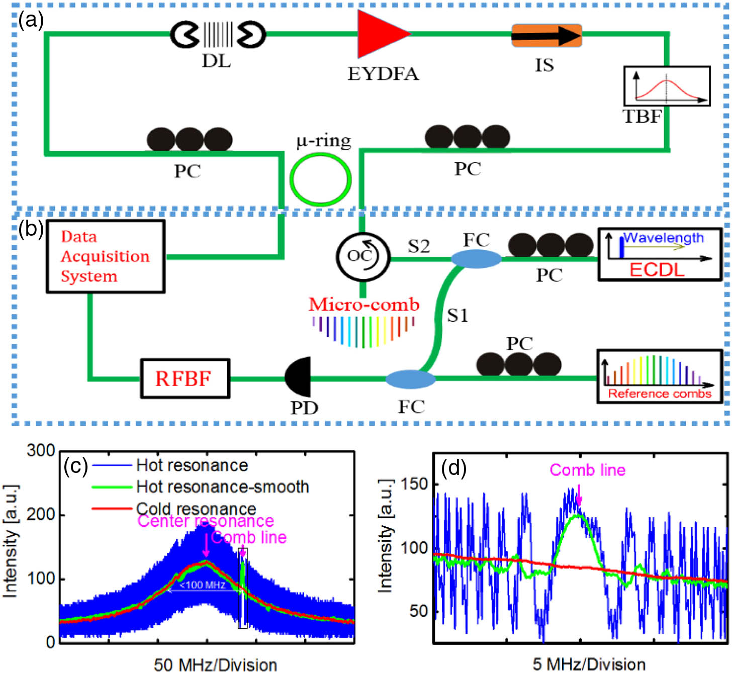
Figure 1.(a) Experimental setup of the FD-FWM laser. In the setup, a nonlinear high- micro-ring resonator is nested in a fiber ring cavity, which contains an optical amplifier (EYDFA), a free-space delay line (DL), a tunable passband filter (TBF), a Faraday isolator (IS), and a polarization controller (PC). (b) Frequency-comb-assisted spectroscopy scheme, which consists of a tunable external cavity diode laser (ECDL) and a reference comb. A scanning CW laser was split into two signals, which are labeled S1 and S2, to perform frequency calibration and the spectroscopy of the micro-ring resonance, respectively. The beating of the tunable laser and the reference comb is extracted with a photodiode (PD) and radio frequency bandpass filter (RFBF). (c) A typical spectroscopy measurement of the micro-cavity resonances and (d) zoom in view. A Lorentzian-shaped resonance (red) combined with the beat note between the probe laser and the oscillating comb line (blue and green). The micro-comb line can be determined by assessing the position where an abrupt phase change takes place, reported in (d), by pink arrow.
The waveguide core is low-loss, high-index-doped () silica glass, buried within a silica cladding and fiber pigtailed to a standard single-mode fiber (SMF) with a typical coupling loss of 1.5 dB/facet. The characteristic resonance linewidth is below 100 MHz and its FSR is at the wavelength of 1550 nm.
The micro-cavity was nested in a fiber-laser–cavity loop, which consisted of an erbium–ytterbium-doped fiber amplifier (EYDFA), a free space delay line, a tunable passband filter, a Faraday isolator, and a polarization controller. The EYDFA was designed to provide relatively large gain and saturation power with a short fiber length (). The free-space delay line controlled the frequency position of the main-cavity modes with respect to the ring resonances and the tunable passband filter (6 nm 3 dB bandwidth) shaped the gain profile and controlled the central oscillating wavelength. The total length of the fiber-laser was , corresponding to a main laser cavity mode spacing of .
To accurately extract the position of the oscillating comb lines, frequency-comb-assisted spectroscopy [50,51] was performed both with no amplification (cold micro-resonator) and during comb generation (hot micro-resonator). A scanning CW laser was split into two signals, S1 and S2. S1 was used to generate a “running” beat note with a reference frequency comb (Menlo Systems GmbH) featured by a repetition rate at 250 MHz and carrier envelope offset frequency at 20 MHz, which are fully stabilized to a GSP-disciplined frequency reference. The beat note was then detected by a photodiode (PD) and sent through one radio frequency (RF) bandpass filter (RFBF) to an oscilloscope, generating calibration markers to precisely extract the scanning laser frequencies. S2 was launched into the through port of the micro-resonator via an optical circulator, to simultaneously perform the spectroscopy of the micro-ring resonance. S2 propagated in the opposite direction to the oscillating micro-comb signal in the resonator and so it interfered with the low-energy, backscattered micro-comb signal, without affecting the system regime.
An example for such a measurement can be seen in Fig. 1(c), showing a bell-shaped resonance profile (red) combined with the beat note between probe laser and oscillating comb line (blue). The micro-comb line location can be determined by assessing the position where the beating experienced an abrupt phase change [see Fig. 1(d)]. It can be seen clearly from Fig. 1(c) that there exists only a single interference region within the micro-resonator resonance, indicating that only one main-cavity mode oscillates within the resonance. This shows that the system was unaffected by the well-known super-mode instability [52,53].
Coherent phase locking could be achieved in the laser system at a multiple of the fundamental repetition rate by careful adjustment of the system parameters, including the use of an appropriate pump power and an accurate positioning of the ring modes with respect to the center of the gain bandwidth, as well as proper phase detuning of the cavity modes relative to the ring resonator mode using the free-space delay line. The coarse dependence on the repetition rate on the fine adjustment of the delay line has been recently discussed in Ref. [48].
Figure 2 shows some of the typical output spectral shapes of the system, with both single [Fig. 2(a)] and multiple FSR frequency spacings [Fig. 2(b)]. Their corresponding autocorrelation (AC) traces are presented in Figs. 2(d) and 2(e). Finally, Fig. 2(c) shows a typical Type-II comb. In the AC [Fig. 2(f)], it can be clearly seen that the pulses of the primary combs () have been modulated by pulses from the sub-combs (). The calculated traces, shown as green dotted lines, were calculated under the assumption that all the oscillating modes were fully coherent and transform limited, a hypothesis that carries good agreement with the measurements. Remarkably, these oscillations could be stable over long time periods without any additional feedback mechanisms.

Figure 2.(a)–(c) Experimental optical spectra and (d)–(f) autocorrelation traces of the laser output for frequency spacings at (a), (d) a single FSR, and (b), (e) multiple FSRs, for the primary comb. (c) and (d) report a Type-II comb.
To better understand the formation of Type-II combs, we closely studied the transition between a Type-I and Type-II comb and determined the positions of the oscillating lines by performing frequency-comb-assisted spectroscopy in a hot micro-resonator.
Here, we first generated a mode locked state at times the fundamental repetition rate of the micro-resonator (see the red dotted line in Fig. 3). Then, a Type-II sub-comb arose after increasing the gain of the amplifier and, consequently, the intra-cavity power, shown as solid lines (various colors). In the transition from Type-I to Type-II comb the intra-cavity power increased by 3.5%.
Figure 3.Experimental optical spectra of the Type-II micro-comb laser output. A mode-locking state at repetition rate (6 times the fundamental repetition rate of the micro-resonator) is overlaid as a red dotted line. The subgroups of Type-II combs around the primary comb lines 1, 7, 13, and 19 are highlighted in black, blue, green, and magenta, respectively.
We then extracted the positions of the oscillating comb lines and micro-ring resonances by performing frequency-comb-assisted spectroscopy in a hot micro-ring resonator. The resonance profile and oscillating comb lines are shown in Figs. 4(a)–4(h), numbered as in Fig. 3. The black dashed line represents the center of the micro-ring resonance.
Figure 4.(a)–(d) Resonance profiles of the primary combs, as numbered in Fig. 3, and (e)–(h) one set of sub-combs around the primary comb line 13.
The oscillating micro-comb line, indicated with a red arrow, corresponds to the region of the beating, exhibiting interference and a phase inversion point [51]. Such lines are easily visible for the cases corresponding to higher intensity modes in Fig. 3, presented in Figs. 4(a)–4(d), where we detected only a single interference point within the micro-cavity resonance. It is interesting to observe that the high-energy modes [Figs. 4(a)–4(d)], were found at the same positions both in the case of the Type-I and Type-II combs in Fig. 3. These modes in general did not fall at the center of the micro-cavity resonance—their position could be finely tuned by adjusting the free-space delay line within the main fiber cavity.
The spectroscopy of the low-energy lines in Figs. 4(e)–4(h) illustrates a larger number of features with additional dips/peaks in the scanning resonance. However, only a single line showing interference and a phase inversion point could be identified, which is indicated with the red arrow. The additional dips, indicated with black arrows, could also be detected when the laser lines in Figs. 4(e)–4(h) were below threshold.
This suggests that only a single line was oscillating within the resonance. We attribute the presence of the additional peaks to a weak backscattering of the scanning laser seeding, non-oscillating main-cavity modes. Remarkably, such a measurement allowed us to also detect the spectral position of these non-oscillating lines. This measurement clearly demonstrates that some of the weak lines were oscillating outside the micro-cavity resonance, although there existed main-cavity modes falling within the micro-ring linewidth.
Better insight into the position of the micro-comb lines can be obtained by plotting the frequency positions of the lines as a function of the comb mode order, as seen in Fig. 5(a). The data can be fit with a straight line with coefficient 48.952 GHz per mode, which represents the average mode spacing of the sub-combs set and corresponds to approximately 660 times the FSR () of the main cavity. The residual plot in Fig. 5(b) shows that different sets of sub-combs shared almost the same mode spacing, but with a mutual offset with respect to each other. Unlike the generation of Type-II combs from micro-resonators via CW laser pumping, the comb lines here were forced by the main-cavity resonances, and, thus, the offset between neighboring sets of sub-combs was equal to an integer multiple of the main-cavity FSR.
Figure 5.(a) Frequency line position versus mode number. Dots are measurements related to the subset around the primary lines 1, 7, 13, and 19 (as highlighted in Fig. 3 and plotted in black, blue, green, and magenta, respectively). Error bars are within the marker size. The results are fitted with a straight line with angular coefficient , which takes into account the error of the measured frequencies due to the accuracy of our frequency-comb-assisted spectroscopy system. (b) Residual plot. Error bars are within the marker size. It shows clearly that all the sub-combs have, within our accuracy, the same FSR but are detuned of 4 times the main-cavity FSR ().
Here, the offset between the neighboring sets of the sub-combs was 4 times the FSR () of the main cavity, which was much larger than the micro-resonator linewidth. In this case, the system did not allow multiple RF beat notes due to the relatively large offset and narrow resonator linewidth, permitting long-term stability.
3. NUMERICAL SIMULATION OF TYPE-II MICRO-COMB GENERATION
The system model is based on the standard coupled equations representing the field evolution and within the micro-ring and fiber cavity, respectively, for the slow and fast cavities times and [44]:
Here, and are the length and the period, respectively, of the amplifying cavity and micro-cavity; , , , and are the gain, gain bandwidth, and the second-order dispersion of the ring and of the fiber, respectively. Also, is the Kerr nonlinear coefficient in the ring. The saturable gain is expressed as where and denote the fiber low-signal gain and gain saturation energy.
The equations are solved in time with a pseudo-spectral method. At the ports of the resonator, the fields are coupled via the relations: where is the ring round trip, is the transmission coefficient [54] and is related to the linewidth and FSR of the ring, and , by the standard relation . The variables and are the phase shifts acquired by the field in half-trip of the ring and a full trip of the fiber, respectively. Equations (4)–(6) are used as boundary conditions for the transverse variable . Here, regulates the position of the main cavity modes with respect to the central ring mode, while dictates the position of the ring modes with respect to the center bandwidth of the gain.
Numerical modeling was performed for a nonlinear micro-ring with FSR 50 GHz and linewidth of 120 MHz, within the experimental range, resulting in a coupling constant . To run the simulations in a reasonable time, we chose an FSR of the fiber cavity approximately 5 times the experimental value (390 MHz). We used dispersion values within our experimental range, and , for the ring and fiber, respectively. Low-power optical noise was used to seed the warmup process of the system.
To match our observed small detuning value in experiment [see Fig. 3(b)], we used the parameter , while, for simplicity, we fixed the first oscillating ring mode at the center of the gain bandwidth, resulting in . As with the experiments, the repetition rate control was realized by changing the fiber laser cavity round trip. In this framework, it is convenient to express the period of the fiber cavity with the following relation: where is an integer, which was fixed in the simulations to 128, and . The parameter , hence, represents the shortening of the fiber round trip in units of ring period, indicating an effective cavity-period detuning. In the simulations, we focus on describing our experimental observation and studying the effect on the solution of the parameter , together with the intra-cavity power.
Figures 6(a)–6(c) report examples of the obtained spectra for a range of cavity-period detunings (, 0.125), resulting in repetition rates of 50, 200, and 400 GHz, respectively [48]. The saturation powers used in Figs. 6(a) and 6(b) were 100 and 2.5 times less than that used in Fig. 6(c).
Figure 6.(a)–(c) Simulated optical spectra and (d)–(f) AC of the laser output with frequency spacing at 1, 4, and 8 FSR. The saturation power ratios are 1, 40, and 100, respectively. The cavity-period detunings (, see text) are 0, 0.25, and 0.125 for (a) and (d), (b) and (e), and (c) and (f), respectively.
Figures 6(d)–6(f) report the AC traces corresponding to Figs. 6(a)–6(c). In these cases, low amplifier saturation energy was chosen so that only primary comb lines appeared in the spectra, and super-modes could be suppressed.
With higher amplifier saturation energy, sub-comb lines were formed with a spacing of 1 FSR of the micro-ring. One typical case, for , is shown in Figs. 7(a)–7(h). The simulation results, including output spectrum and intensity as well as AC, are plotted for the system as a function of increasing saturation energy. Here, Fig. 7(a) corresponds to the case of Fig. 6(c).
Figure 7.(a)–(d) Simulated optical spectra, (e)–(h) AC (blue) and normalized temporal evolution of the intensity (red) of 8 FSR primary combs and Type-II combs. Here, the saturation powers are in a ratio 1, 2, 2.5, 3.5 for (a) and (e), (b) and (f), (c) and (g), and (d) and (h), respectively.
Saturation energies in Figs. 7(b)–7(d) are 2, 2.5, and 3.5 times the corresponding value in Fig. 7(a), respectively. Initially, primary comb lines in the spectrum were gradually formed with increasing amplifier saturation energy, where the central wavelengths transferred their energy to side wavelengths through the FWM effect. With a higher amplifier saturation energy, sub-comb lines develop and fill in between the primary comb lines spaced by 1 micro-ring FSR. For this kind of generation, the AC traces do not always show high contrast although coherent pulses are generated.
4. CONCLUSION
We demonstrate the generation of Type-II micro-combs in a filter-driven four wave mixing laser. The system produces a robust comb that can be formed, starting from a primary comb, by adjusting the gain of the laser amplifier. This was confirmed by numerical simulations. Our experimental study shows that the spacing between the comb lines can be controlled by adjusting the fiber cavity length. Our study constitutes a significant contribution to understanding the dynamics of the FD-FWM laser, and a step toward the generation of stable and controllable optical combs from an integrated chip-based resonator.
Acknowledgment
Acknowledgment. We acknowledge the support of the U.K. Quantum Technology Hub for Sensors and Metrology, EPSRC, of the Marie Curie Action MC-CIG and MC-IIF and of the ERC-CoG. R. Morandotti acknowledges support from the CRC, NSERC, and MEIE, the ITMO and its Professorship Program, as well as the 1000 Talents Sichuan Program, China.
The data sets for all the figures are freely accessible at https://doi.org/10.6084/m9.figshare.5856489 (doi: 10.6084/m9.figshare.5856489).
References
[1] A. Pasquazi, M. Peccianti, L. Razzari, D. J. Moss, S. Coen, M. Erkintalo, Y. K. Chembo, T. Hansson, S. Wabnitz, P. Del’Haye, X. Xue, A. M. Weiner, R. Morandotti. Micro-combs: a novel generation of optical sources. Phys. Rep., 729, 1-81(2018).
[2] T. J. Kippenberg, R. Holzwarth, S. Diddams. Microresonator-based optical frequency combs. Science, 332, 555-559(2011).
[3] J. Pfeifle, V. Brasch, M. Lauermann, Y. Yu, D. Wegner, T. Herr, K. Hartinger, P. Schindler, J. Li, D. Hillerkuss, R. Schmogrow, C. Weimann, R. Holzwarth, W. Freude, J. Leuthold, T. Kippenberg, C. Koos. Coherent terabit communications with microresonator Kerr frequency combs. Nat. Photonics, 8, 375-380(2014).
[4] J. Pfeifle, A. Coillet, R. Henriet, K. Saleh, P. Schindler, C. Weimann, W. Freude, I. V. Balakireva, L. Larger, C. Koos, Y. K. Chembo. Optimally coherent Kerr combs generated with crystalline whispering gallery mode resonators for ultrahigh capacity fiber communications. Phys. Rev. Lett., 114, 093902(2015).
[5] P. Marin-Palomo, J. N. Kemal, M. Karpov, A. Kordts, J. Pfeifle, M. H. Pfeiffer, P. Trocha, S. Wolf, V. Brasch, M. H. Anderson, R. Rosenberger, K. Vijayan, W. Freude, T. J. Kippenberg, C. Koos. Microresonator-based solitons for massively parallel coherent optical communications. Nature, 546, 274-279(2017).
[6] M.-G. Suh, Q.-F. Yang, K. Y. Yang, X. Yi, K. J. Vahala. Microresonator soliton dual-comb spectroscopy. Science, 354, 600-603(2016).
[7] S. B. Papp, K. Beha, P. Del’Haye, F. Quinlan, H. Lee, K. J. Vahala, S. A. Diddams. Microresonator frequency comb optical clock. Optica, 1, 10-14(2014).
[8] F. Ferdous, H. Miao, D. E. Leaird, K. Srinivasan, J. Wang, L. Chen, L. T. Varghese, A. M. Weiner. Spectral line-by-line pulse shaping of on-chip microresonator frequency combs. Nat. Photonics, 5, 770-776(2011).
[9] C. Reimer, M. Kues, P. Roztocki, B. Wetzel, F. Grazioso, B. E. Little, S. T. Chu, T. Johnston, Y. Bromberg, L. Caspani, D. J. Moss, R. Morandotti. Generation of multiphoton entangled quantum states by means of integrated frequency combs. Science, 351, 1176-1180(2016).
[10] M. Kues, C. Reimer, P. Roztocki, L. Romero Cortés, S. Sciara, B. Wetzel, Y. Zhang, A. Cino, S. T. Chu, B. E. Little, D. J. Moss, L. Caspani, J. Azaña, R. Morandotti. On-chip generation of high-dimensional entangled quantum states and their coherent control. Nature, 546, 622-626(2017).
[11] P. Del’Haye, A. Schliesser, O. Arcizet, T. Wilken, R. Holzwarth, T. Kippenberg. Optical frequency comb generation from a monolithic microresonator. Nature, 450, 1214-1217(2007).
[12] T. Herr, K. Hartinger, J. Riemensberger, C. Wang, E. Gavartin, R. Holzwarth, M. Gorodetsky, T. Kippenberg. Universal formation dynamics and noise of Kerr-frequency combs in microresonators. Nat. Photonics, 6, 480-487(2012).
[13] T. Herr, V. Brasch, J. D. Jost, C. Y. Wang, N. M. Kondratiev, M. L. Gorodetsky, T. J. Kippenberg. Temporal solitons in optical microresonators. Nat. Photonics, 8, 145-152(2014).
[14] H. Guo, M. Karpov, E. Lucas, A. Kordts, M. H. Pfeiffer, V. Brasch, G. Lihachev, V. E. Lobanov, M. L. Gorodetsky, T. J. Kippenberg. Universal dynamics and deterministic switching of dissipative Kerr solitons in optical microresonators. Nat. Phys., 13, 94-102(2017).
[15] M. Karpov, H. Guo, A. Kordts, V. Brasch, M. H. P. Pfeiffer, M. Zervas, M. Geiselmann, T. J. Kippenberg. Raman self-frequency shift of dissipative Kerr solitons in an optical microresonator. Phys. Rev. Lett., 116, 103902(2016).
[16] P. Del’Haye, T. Herr, E. Gavartin, M. Gorodetsky, R. Holzwarth, T. Kippenberg. Octave spanning tunable frequency comb from a microresonator. Phys. Rev. Lett., 107, 063901(2011).
[17] J. S. Levy, A. Gondarenko, M. A. Foster, A. C. Turner-Foster, A. L. Gaeta, M. Lipson. CMOS-compatible multiple-wavelength oscillator for on-chip optical interconnects. Nat. Photonics, 4, 37-40(2010).
[18] D. J. Moss, R. Morandotti, A. L. Gaeta, M. Lipson. New CMOS-compatible platforms based on silicon nitride and Hydex for nonlinear optics. Nat. Photonics, 7, 597-607(2013).
[19] K. Y. Yang, K. Beha, D. C. Cole, X. Yi, P. Del’Haye, H. Lee, J. Li, D. Y. Oh, S. A. Diddams, S. B. Papp, K. J. Vahala. Broadband dispersion-engineered microresonator on a chip. Nat. Photonics, 10, 316-320(2016).
[20] P. Del’Haye, A. Coillet, T. Fortier, K. Beha, D. C. Cole, K. Y. Yang, H. Lee, K. J. Vahala, S. B. Papp, S. A. Diddams. Phase-coherent microwave-to-optical link with a self-referenced microcomb. Nat. Photonics, 10, 516-520(2016).
[21] A. B. Matsko, W. Liang, A. A. Savchenkov, L. Maleki. Chaotic dynamics of frequency combs generated with continuously pumped nonlinear microresonators. Opt. Lett., 38, 525-527(2013).
[22] C. Bao, J. A. Jaramillo-Villegas, Y. Xuan, D. E. Leaird, M. Qi, A. M. Weiner. Observation of Fermi-Pasta-Ulam recurrence induced by breather solitons in an optical microresonator. Phys. Rev. Lett., 117, 163901(2016).
[23] M. Yu, J. K. Jang, Y. Okawachi, A. G. Griffith, K. Luke, S. A. Miller, X. Ji, M. Lipson, A. L. Gaeta. Breather soliton dynamics in microresonators. Nat. Commun., 8, 14569(2017).
[24] S.-W. Huang, J. Yang, S.-H. Yang, M. Yu, D.-L. Kwong, T. Zelevinsky, M. Jarrahi, C. W. Wong. Globally stable microresonator Turing pattern formation for coherent high-power THz radiation on-chip. Phys. Rev. X, 7, 041002(2017).
[25] S. B. Papp, P. Del’Haye, S. A. Diddams. Parametric seeding of a microresonator optical frequency comb. Opt. Express, 21, 17615-17624(2013).
[26] S.-W. Huang, H. Zhou, J. Yang, J. F. McMillan, A. Matsko, M. Yu, D.-L. Kwong, L. Maleki, C. W. Wong. Mode-locked ultrashort pulse generation from on-chip normal dispersion microresonators. Phys. Rev. Lett., 114, 053901(2015).
[27] Y. Liu, Y. Xuan, X. Xue, P.-H. Wang, S. Chen, A. J. Metcalf, J. Wang, D. E. Leaird, M. Qi, A. M. Weiner. Investigation of mode coupling in normal-dispersion silicon nitride microresonators for Kerr frequency comb generation. Optica, 1, 137-144(2014).
[28] P. Del’Haye, K. Beha, S. B. Papp, S. A. Diddams. Self-injection locking and phase-locked states in microresonator-based optical frequency combs. Phys. Rev. Lett., 112, 043905(2014).
[29] L. Razzari, D. Duchesne, M. Ferrera, R. Morandotti, S. Chu, B. Little, D. Moss. CMOS-compatible integrated optical hyper-parametric oscillator. Nat. Photonics, 4, 41-45(2010).
[30] W. Liang, D. Eliyahu, V. Ilchenko, A. Savchenkov, A. Matsko, D. Seidel, L. Maleki. High spectral purity Kerr frequency comb radio frequency photonic oscillator. Nat. Commun., 6, 7957(2015).
[31] V. Brasch, M. Geiselmann, T. Herr, G. Lihachev, M. H. P. Pfeiffer, M. L. Gorodetsky, T. J. Kippenberg. Photonic chip-based optical frequency comb using soliton Cherenkov radiation. Science, 351, 357-360(2016).
[32] C. Y. Wang, T. Herr, P. Del’Haye, A. Schliesser, J. Hofer, R. Holzwarth, T. W. Hänsch, N. Picqué, T. J. Kippenberg. Mid-infrared optical frequency combs at 2.5 μm based on crystalline microresonators. Nat. Commun., 4, 1345(2013).
[33] Y. K. Chembo, D. V. Strekalov, N. Yu. Spectrum and dynamics of optical frequency combs generated with monolithic whispering gallery mode resonators. Phys. Rev. Lett., 104, 103902(2010).
[34] I. S. Grudinin, L. Baumgartel, N. Yu. Frequency comb from a microresonator with engineered spectrum. Opt. Express, 20, 6604-6609(2012).
[35] I. S. Grudinin, V. S. Ilchenko, L. Maleki. Ultrahigh optical Q factors of crystalline resonators in the linear regime. Phys. Rev. A, 74, 063806(2006).
[36] M. Yu, Y. Okawachi, A. G. Griffith, M. Lipson, A. L. Gaeta. Mode-locked mid-infrared frequency combs in a silicon microresonator. Optica, 3, 854-860(2016).
[37] H. Jung, C. Xiong, K. Y. Fong, X. Zhang, H. X. Tang. Optical frequency comb generation from aluminum nitride microring resonator. Opt. Lett., 38, 2810-2813(2013).
[38] M. Pu, L. Ottaviano, E. Semenova, K. Yvind. Efficient frequency comb generation in AlGaAs-on-insulator. Optica, 3, 823-826(2016).
[39] M. Haelterman, S. Trillo, S. Wabnitz. Dissipative modulation instability in a nonlinear dispersive ring cavity. Opt. Commun., 91, 401-407(1992).
[40] F. Leo, S. Coen, P. Kockaert, S.-P. Gorza, P. Emplit, M. Haelterman. Temporal cavity solitons in one-dimensional Kerr media as bits in an all-optical buffer. Nat. Photonics, 4, 471-476(2010).
[41] S. Coen, M. Erkintalo. Universal scaling laws of Kerr frequency combs. Opt. Lett., 38, 1790-1792(2013).
[42] A. Coillet, Y. K. Chembo. Routes to spatiotemporal chaos in Kerr optical frequency combs. Chaos, 24, 013113(2014).
[43] C. Bao, P. Liao, A. Kordts, L. Zhang, M. Karpov, M. Pfeiffer, Y. Cao, Y. Yan, A. Almaiman, G. Xie, A. Mohajerin-Ariaei, L. Li, M. Ziyadi, S. Wilkinson, M. Tur, T. Kippenberg, A. Willner. Dual-pump generation of high-coherence primary Kerr combs with multiple sub-lines. Opt. Lett., 42, 595-598(2017).
[44] M. Peccianti, A. Pasquazi, Y. Park, B. E. Little, S. T. Chu, D. J. Moss, R. Morandotti. Demonstration of a stable ultrafast laser based on a nonlinear microcavity. Nat. Commun., 3, 765(2012).
[45] A. Pasquazi, M. Peccianti, B. E. Little, S. T. Chu, D. J. Moss, R. Morandotti. Stable, dual mode, high repetition rate mode-locked laser based on a microring resonator. Opt. Express, 20, 27355-27362(2012).
[46] A. Pasquazi, L. Caspani, M. Peccianti, M. Clerici, M. Ferrera, L. Razzari, D. Duchesne, B. E. Little, S. T. Chu, D. J. Moss, R. Morandotti. Self-locked optical parametric oscillation in a CMOS compatible microring resonator: a route to robust optical frequency comb generation on a chip. Opt. Express, 21, 13333-13341(2013).
[47] W. Q. Wang, S. T. Chu, B. E. Little, A. Pasquazi, Y. S. Wang, L. R. Wang, W. F. Zhang, L. Wang, X. H. Hu, G. X. Wang, H. Hu, Y. L. Su, F. T. Li, Y. S. Liu, W. Zhao. Dual-pump Kerr micro-cavity optical frequency comb with varying FSR spacing. Sci. Rep., 6, 28501(2016).
[48] W. Q. Wang, W. F. Zhang, S. T. Chu, B. E. Little, Q. H. Yang, L. R. Wang, X. H. Hu, L. Wang, G. X. Wang, Y. H. Wang, W. Zhao. Repetition rate multiplication pulsed laser source based on a micro-ring resonator. ACS Photon., 4, 1677-1683(2017).
[49] L. Di Lauro, J. Li, D. J. Moss, R. Morandotti, S. T. Chu, M. Peccianti, A. Pasquazi. Parametric control of thermal self-pulsation in micro-cavities. Opt. Lett., 42, 3407-3410(2017).
[50] P. Del’Haye, O. Arcizet, M. L. Gorodetsky, R. Holzwarth, T. J. Kippenberg. Frequency comb assisted diode laser spectroscopy for measurement of microcavity dispersion. Nat. Photonics, 3, 529-533(2009).
[51] P. Del’Haye, A. Coillet, W. Loh, K. Beha, S. B. Papp, S. A. Diddams. Phase steps and resonator detuning measurements in microresonator frequency combs. Nat. Commun., 6, 5668(2015).
[52] J. Schröder, T. D. Vo, B. J. Eggleton. Repetition-rate-selective, wavelength-tunable mode-locked laser at up to 640 GHz. Opt. Lett., 34, 3902-3904(2009).
[53] J. Schröder, D. Alasia, T. Sylvestre, S. Coen. Dynamics of an ultrahigh-repetition-rate passively mode-locked Raman fiber laser. J. Opt. Soc. Am. B, 25, 1178-1186(2008).
[54] B. E. Little, S. T. Chu, H. A. Haus, J. Foresi, J.-P. Laine. Microring resonator channel dropping filters. J. Lightwave Technol., 15, 998-1005(1997).


