RuHai Guo, "Analysis of laser beam propagation properties with the Collins formula in a focused laser system," Chin. Opt. Lett. 13, S21408 (2015)
Copy Citation Text
A Collins formula method with a scaling factor between the target and source plane is proposed for laser propagation in optical system design, which can be used to evaluate laser optical system performance and tolerance analysis. The laser propagation in optical systems can be calculated by the Collins integral formula, and an angular spectrum method is derived by coordinate substitution. It is introduced a scaling factor m, making the choice of the observation plane more flexible and the calculation more accurate. A laser optical system is designed, and its tolerance analysis is conducted by the angular spectrum method. The evaluation criterion is the laser spot radius in the far-field, which is defined by 86.5% power in bucket. The radius of the laser spot in 90 m distance is from 0.8 to 1.4 mm by the tolerance analysis, which the ideal expectation is 0.92 mm and the experimental result is 1.01 mm. In the distance of 47 m, the radius is from 0.42 to 0.73 mm by the tolerance analysis, which the ideal expectation is 0.48 mm and the experimental result is 0.46 mm. The experimental results agree with the results of the tolerance analysis well. The focal shift for laser propagation in optical systems is validated. The experimental results confirm the calculation and they prove the use of the method in laser focus optical system design.
The propagation problem of light can be solved by the Fresnel or Fraunhofer diffraction integral[1]. The Collins formula can be regarded as the powerful tool[2–4] to study laser propagation after the optical system. The aberration of an optical system can be introduced into the Collins formula and directly adding to the integral for the investigation of transmission properties in laser beams with aberration[5,6]. Based on the Collins formula, using the angular spectral method and coordinate transformation to realize the freedom of sampling rate choosing, the laser optical system design is achieved by the evaluation standard of the spot radius [power in bucket (PIB) of 86.5%].
The Collins formula is as follows[7]where , , , and are the elements of the optical system matrix. is the complex amplitude distribution of the incident light, is the wavelength, and is the wave vector. The Collins formula can be transferred to the formation of convolution by a coordinate transformation ππ
From the convolution theorem, the solution of Eq. (2) can be realized by the Fourier and inverse Fourier transform. However, this algorithm cannot control the sampling interval of the target plane. When the laser beam focuses into a point, this will render the calculation invalid. Therefore, a scaling factor is introduced to zoom the source plane of incident light and the target plane so that the detail of focus spot can be provided Then Eq. (2) can be calculated
Sign up for Chinese Optics Letters TOC. Get the latest issue of Chinese Optics Letters delivered right to you!Sign up now
The coordinate after scaling is
Therefore, Equation (6) is only applicable to an ideal paraxial optical system. In order to describe the real optical system, an aberration term must be added into Eq. (1) πwhere is the wave aberration.
Providing a real optical system, after a distance propagation, the matrix is
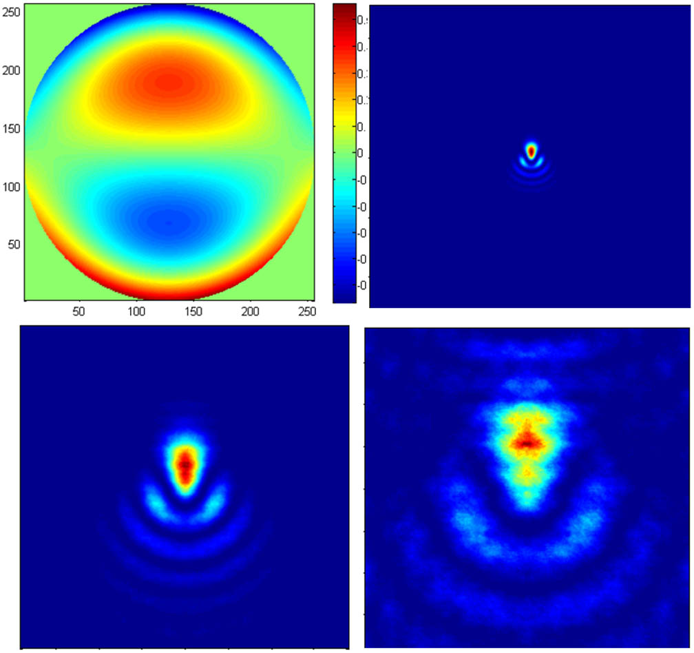
The optical intensity distribution is shown in Fig. 1 with the aberration. With different values of , the detailed optical intensity distribution in the focus plane is shown. From Fig. 1, the optical system has coma error and its RMS is . This optical system also contains astigmatism and its RMS is also (Fig. 2). Therefore, through choosing a suitable m, we can amplify the target plane just enough to including the focus light spot.
Figure 1.Coma wavefront error and the resulting laser spot distribution with different scaling factors.
The optical system design software Zemax is used to design the laser focus system. However, the software is based on ray tracing, such that it cannot analyze the optical intensity distribution after laser beam propagation through an aberration optical system. If we take the aforementioned Collins formula [Eq. (1)] to solve this problem, both the geometry optical effects and the diffraction effects will be considered. Through the tolerance analysis of Zemax, the aberration of the focus system can be obtained, which will be added into Eq. (7) to obtain the optical intensity distribution after the focused optical system (Fig. 3). Its aperture is 100 m, and the focus range is from 30 to 100 m. The focus position is adjusted by the distance between the front lens and back lens.
Figure 3.Ensemble framework of our laser optical system.
Figure 4 shows the focus optical spot distribution and PIB with a distance 90 m and a RMS wavefront error . The spot radius is 1.05 mm larger than the ideal radius 0.52 mm because the aberration enlarges the radius of spot.
Figure 4.Wavefront with tolerance and the resulting laser spot distribution and PIB curve.
The distance of the lens can be adjusted to compensate the focus shift and calibrated by a 1000 Ω electric displacement meter. The calibrating accuracy is 5 μm and the range is from to 20 μm. The results are shown in Fig. 5.
Figure 5.Laser spot radius with compensation error.
When the RMS wavefront errors are equal, the spot radius with negative focus compensation is larger than the radius with positive focus compensation. This can be explained by Fig. 6 with two sets of RMS wavefront errors . The difference is only because the laser beam satisfies a Gaussian distribution. Therefore, the waist of the beam will not coincide with the focus of the optical system.
Figure 6.PIB curve with positive compensation error and negative compensation error.
The experimental setup is shown in Fig. 7. The 532 nm laser first propagates through the expander and then incidents into the designed focus optical system.
The light spot is focused at 90 m from the laser source through adjusting the distance between the front lens and the back lens. The recording device is a CCD detector with pixel size μμ. The spot radius can be obtained by calculating the pixel number occupied by the spot. The results show that the spot radius is 1.10 mm with PIB 86.5% (Fig. 8). This result closely agrees with the theoretical analysis. The discrepancy mainly comes from the laser shift and the vibration of the platform.
Figure 8.Measured laser spot radius at the distance of 90 m.
In laser propagation, the optical design software Zemax cannot fully evaluate the optical intensity distribution because of the diffraction effects and the aberration. Furthermore, the laser beam is like a Gaussian profile, not a plane wave. A method that uses the Collins formula with a scaling factor is presented in this Letter to compensate this shortcoming of optical design. The optical aberration is readily added into the integral to obtain the focused light spot intensity distribution over an arbitrary distance. An example of a focus system is provided to focus a laser beam from 30 to 100 m. The theoretical results show that the spot radius is 1.05 mm at the distance 90 m, which agrees well with the experimental results. This verifies the effectiveness of our algorithm, which can be applied in the design of a laser propagation system.
References
[1] X. H. Zhong. Foundation of Modern Optics, 60(2011).