1Electronic Information School, Wuhan University, Wuhan 430072, China
2NOEIC, State Key Laboratory of Optical Communication Technologies and Networks, Wuhan Research Institute of Posts and Telecommunications, Wuhan 430074, China
3School of Physics and Technology, Center for Nanoscience and Nanotechnology, and Key Laboratory of Artificial Micro- and Nano-structures of Ministry of Education, Wuhan University, Wuhan 430072, China
The unwanted zero-order light accompanied by the birth of diffractive optical elements and caused mainly by fabrication errors and wavelength variations is a key factor that deteriorates the performance of diffraction-related optical devices such as holograms, gratings, beam shapers, beam splitters, optical diffusers, and diffractive microlenses. Here, inspired by the unique characteristic of nano-polarizer-based metasurfaces for both positive and negative amplitude modulation of incident light, we propose a general design paradigm to eliminate zero-order diffraction without burdening the metasurface design and fabrication. The experimentally demonstrated meta-hologram, which projects a holographic image with a wide angle of in the far field, presents a very low zero-order intensity (only 0.7% of the total energy of the reconstructed image). More importantly, the zero-order-free meta-hologram has a large tolerance limit for wavelength variations (under a broadband illumination from 520 to 660 nm), which brings important technical advances. The strategy proposed could significantly relieve the fabrication difficulty of metasurfaces and be viable for various diffractive-optics-related applications including holography, laser beam shaping, optical data storage, vortex beam generation, and so on.
1. INTRODUCTION
In conventional hologram designs, the intensity profile is controlled by recording the interference fringes of an object and reference waves on a plate coating with photosensitive material [1–3]. Therefore, the reconstructed image contains both the target image and the reference wave, and the latter contributes to the unwanted zero-order diffraction light. Since the intensity of zero-order light is generally at the level of the sum of signal image intensity, it could dramatically lower the signal-to-noise ratio and diffractive efficiency. In the past decades, phase-only holograms based on diffractive optical elements (DOEs) [4–8] have been developed and applied in many fields of diffraction optics such as imaging, laser beam shaping, and sensing. The phase-only holograms hold unique features of high diffractive efficiency and elimination of zero-order light in principle. However, almost all the holograms reported so far have to contain a dazzling spot in the image center [7–10], which dramatically degrades the visual effect and performance for practical applications. The strong zero-order light is the result of the unmodulated light in the overall pixels of the DOEs accumulating in the zero-order diffraction direction rather than dispersing in the space as noise light, and therefore very small fabrication errors and wavelength fluctuations could cause an avalanche amplification of zero-order light intensity. In recent years, meta-holograms based on Pancharatnam–Berry (PB) phase have been studied widely. It is generally known that PB phase does not depend on the working wavelength [11–14]; however, the intensity of the unconverted circularly polarized (CP) light giving rise to the zero-order light will increase dramatically if the working wavelength is far away from the design wavelength or the nanostructure deviates from a half-wave plate due to fabrication errors. In experiments of collecting the holographic image [14], a laser source has to be converted to CP light using a linear polarizer and a quarter-wave plate before illuminating the meta-hologram as required by the PB phase. Additionally, a quarter-wave plate and an analyzer have to be placed behind the meta-hologram to filter out the zero-order light caused by the transmitted CP light with the same handedness of the input light. Overall, the whole optical setup is complicated, and the working bandwidth of the meta-hologram is restricted by the spectrum bandwidth of the quarter-wave plate. The same problem occurs in metalenses. Different from holograms, the zero-order light of a metalens covers almost the whole image area, and one also has to use a complex optical setup to filter out the zero-order light for a practical purpose [15]. Therefore, eliminating zero-order light is still a critical issue to be solved for both conventional DOEs and metasurfaces.
Recently, metasurfaces consisting of nanostructure arrays with different orientations have been reported for ultracompact image display [16–19], which indicates a promising approach to realize precise amplitude manipulation of incident light with subwavelength resolution. Inspired by Malus’s law for determining the output amplitude and intensity under linearly polarized (LP) light incidence, we found that nano-polarizer-based metasurfaces have a unique characteristic of both positive and negative amplitude modulation and can be employed to eliminate zero-order diffraction without burdening the metasurface design and fabrication. Nano-polarizers generally refer to metal [17] or dielectric [18] nanobricks, which can transmit most of the incident light polarized along the short-axis direction while reflecting that along the orthogonal direction. Since the nano-polarizer can be rotated in an interval of 0°–360°, each nano-polarizer has at least two orientation candidates to generate positive or negative amplitudes corresponding to an equal output intensity. Compared with conventional amplitude-only holograms, which can only generate positive amplitudes (and therefore the sum of all unmodulated light amplitude has to be positive, accounting for the strong zero-order light), the new strategy can gift the unmodulated light either positive or negative amplitude modulation. Therefore, carefully reconfiguring the orientations of nano-polarizers is a promising way to find a solution to make the amplitudes of all unmodulated light add up to zero. This forms the basis of eliminating zero-order diffraction of amplitude-only meta-holograms.
More importantly, as the transmitted light is only related to the orientations of nanobricks, the fabrication errors or wavelength variations affect the transmission efficiency rather than zero-order intensity. This unique feature is quite different from conventional DOEs or previous metasurfaces [20–22], which always suffer from the dramatically increased zero-order intensity because of a small fabrication error or wavelength fluctuation.
Sign up for Photonics Research TOC. Get the latest issue of Photonics Research delivered right to you!Sign up now
To verify our proposed approach, we designed and fabricated an in-line meta-hologram with elimination of zero-order diffraction. The experimental results indicate that a holographic image with a wide image angle of is achieved with satisfactory performance, and the zero-order diffraction intensity can be restricted to only 0.7% of the total transmitted energy. Moreover, we used a supercontinuum laser source over a wavelength range from 520 to 660 nm to illuminate the fabricated sample. All of the holographic images reconstructed by various operating wavelengths are clearly observed with limited zero-order light diffraction, which verifies that the zero-order-free meta-hologram works quite well in a broadband visible range.
2. WORKING PRINCIPLE OF ZERO-ORDER-FREE META-HOLOGRAMS
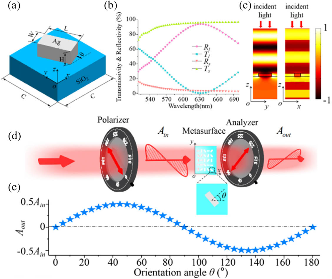
The proposed zero-order-free meta-hologram is composed of silver nanobrick arrays sitting on a planar silica substrate. All of the nanobricks have identical geometry parameters (cell size , height , width , and length ) but different orientation angles (the angle between the short axis of the nanobrick and the axis). The schematic diagram of an anisotropic nanostructure is illustrated in Fig. 1(a). The nanobrick can generate unequal electromagnetic responses along the short and long axes due to the dimension difference in two orthogonal directions. As a consequence, we can control the anisotropy by adjusting the geometry parameters of a nanostructure. Here, the CST Microwave Studio software was used to simulate and optimize the nanostructure. In the simulations, a normally incident LP plane wave polarized along the short or long axis of a nanobrick was employed to illuminate a nanobrick unit cell with periodic boundary conditions. By carefully designing the geometric dimensions, the silver nanobrick is designed with of 300 nm, of 80 nm, of 80 nm, and of 160 nm. With these geometric parameters and orientation fixed at 0°, the corresponding transmissivities , and reflectivities , of the nanostructure versus wavelength are plotted in Fig. 1(b). At the design wavelength of 632.8 nm, and reach 90%, while and are lower than 3%. The simulated results of the electric field distributions at the cross section and of the nanobrick are shown in Fig. 1(c). From Figs. 1(b) and 1(c), it can also be seen that the incident light with the electric-field direction along the long axis is almost reflected, while the incident light polarized along the orthogonal direction is almost transmitted. Therefore, the designed nanostructure can act as a linear polarizer in transmission or reflection mode.
Figure 1.Illustration of both positive and negative amplitude modulation of the nanobrick-based metasurface. (a) Schematic of a nanobrick unit cell. The nanobrick can be rotated in the plane with an orientation angle . (b) Transmissivity and reflectivity versus wavelength (520–700 nm), where and denote the polarization directions of the normally incident light along the short and long axes of the nanobrick, respectively. (c) Electric field distribution in the nanostructure with incident light polarized along the long or short axis, respectively. The orientation angle in (b) and (c) is 0°. (d) Illustration of the optical setup for continuous amplitude modulation. (e) Output light amplitudes versus orientation angles.
Next, we insert the nano-polarizer-based metasurface into an orthogonal-polarization optical path as illustrated in Fig. 1(d). The red two-way arrows represent the transmission axes of the linear polarizer and analyzer, respectively. According to Malus’s law, we can readily derive the equation of output light amplitude as where and are the complex transmission coefficients of a nanobrick along the short and long axes, respectively, is the in-plane orientation angle of a nanobrick, and is the amplitude of transmitted light after the polarizer.
If the nanobrick acts as an ideal linear polarizer (i.e., and ), Eq. (1) can be simplified as . As shown in Fig. 1(e), a continuous amplitude modulation of the incident light can be obtained cell by cell by varying the orientations of the nanobricks. It is worth noting that the transmitted amplitude of light can be either positive or negative, which is unavailable for conventional amplitude-only optical devices since they modulate the light intensity rather than amplitude. Therefore, it provides a method to eliminate the useless zero-order light mixed into the reconstructed image by elaborately redesigning the amplitude distribution of a meta-hologram consisting of the nanobricks mentioned above.
3. THEORETICAL ANALYSIS AND SIMULATIONS OF THE ZERO-ORDER-FREE META-HOLOGRAM
At first, the original non-negative amplitude distribution matrix (the interval of definition is [0,1]) of a digital hologram is calculated by some design algorithms such as a simulated annealing algorithm [23] according to a target image. By this step, a conventional digital hologram is designed. According to digital Fourier holography, the amplitude distribution of the reconstructed image computed by a discrete Fourier transformation (DFT) algorithm can be expressed as where (, ) and (, ) represent the rectangular coordinates in the recorded plane and the reconstructed plane, respectively, and and denote the pixel numbers of the digital hologram along the and axes, respectively.
Therefore, the amplitude of zero-order diffraction of the conventional digital hologram is given as In Eq. (3), we can see that the amplitude of zero-order diffraction is essentially the sum of the original amplitude matrix , which is a very large value because the amplitude of each pixel of the conventional hologram is always non-negative (positive or zero). The simulated results of the conventional digital hologram with non-negative amplitude modulation are shown in Fig. 2(a). We can see that one has to endure a very strong spot in the central position of the reconstructed image, which overwhelms the signal image and significantly lowers the visual effect. As the intensity of zero-order light occupies the main energy (95.6%) of the output light and its order of magnitude is much larger than that of any other diffraction orders of the holographic image, we have to use the common logarithm (logarithm with base 10) to intuitively describe the normalized intensity distribution of the image. Figure 2(c) shows the corresponding 3D intensity distribution, and there is a very sharp spike in the center.
Figure 2.Comparison of a conventional digital hologram with a zero-order-free meta-hologram. (a) A conventional digital hologram with amplitude distribution in an interval of [0,1]. (b) An enlarged view of the partial amplitude distribution. (c) The 3D intensity distribution of the reconstructed image containing strong zero-order light. (d) A zero-order-free meta-hologram with amplitude distribution in an interval of [, 0.5]. (e) An enlarged view of the partial amplitude distribution. (f) The 3D intensity distribution of the holographic image without the zero-order light.
Now we demonstrate how to eliminate the zero-order light. In our design, each element of the calculated original amplitude matrix subtracts the average value of the matrix () to form a new amplitude matrix of the zero-order-free meta-hologram as shown in Fig. 2(b). The corresponding new amplitude distribution of the reconstructed image can now be written as As a result, the new amplitude of zero-order is equal to zero, and therefore the zero-order light is eliminated. Figure 2(d) shows the simulated results of the zero-order-free meta-hologram, and the reconstructed image is clear with no interference of the zero-order light. The corresponding 3D intensity distribution in Fig. 2(f) also verifies that the intensity of the zero-order light is equal to zero, which is consistent with the theoretical analysis.
The design strategy we proposed is effective to suppress the zero-order light of holograms, and it is easy to achieve by utilizing the positive and negative amplitude modulation mapping diagram shown in Fig. 1(b). The new amplitudes can be elaborately encoded into orientation angles of nanostructures mentioned above to form a meta-hologram free of zero-order light. In our design, each nanostructure can act as an ideal linear polarizer (i.e., and ). As a result, the orientation angle matrix of the nano-polarizer-based meta-holograms can be derived as The proposed zero-order-free meta-hologram has a unique characteristic that it can resist fabrication errors and wavelength fluctuations. A nanobrick with fabrication errors or wavelength fluctuations would deviate from an ideal nano-polarizer, and therefore the complex transmission coefficients of the nanobrick ( and ) will vary. If we go back to observe Eq. (1), it can be found that the varied and do influence the amplitude modulation. However, the influence for each pixel of the meta-hologram is the same, and therefore the amplitude modulation rule of the metasurface remains steady except for the varied transmission efficiency. Furthermore, even if each nanobrick of the meta-hologram has different complex transmission coefficients and due to the nonuniform fabrication errors, the amplitude of zero-order light (i.e., the sum of the output light amplitude of each pixel) could be efficiently suppressed, as can be either positive or negative.
This interesting and important characteristic is quite different from conventional DOEs and metasurfaces. For conventional DOEs [4,5] and metasurfaces with propagation phase [24–27], geometric phase [11–14,28,29], or their combination [30,31], the phase profiles are controlled by etching different pixel depths [4,5], dimension-varied nanostructures [24–27], or orientation-controlled nanostructures [11–14,28,29]. Therefore, a small dimension error or wavelength fluctuation would have a slight influence on the holographic image. The reason is that there is an “N-to-N” mapping between DOE/metasurface pixels and holographic image pixels for modulated light, where N is the pixel number of the DOE/metasurface in one dimension (1D). Therefore, the “errors” are mixed into the diffraction light, and they are almost uniformly mapped into every pixel of the holographic image, which would have a slight influence on the hologram’s performance. However, the zero-order light is generated by an “N-to-1” mapping, since the unmodulated light of all pixels accumulates in the zero-order diffraction direction rather than scattering into the image space. As a result, the zero-order intensity will dramatically increase, even with a very small fabrication error or wavelength fluctuation. This is a basic drawback of conventional DOEs/metasurfaces, and it has been almost unavoidable until now. As a solution, off-axis design is widely adopted to avoid the overlapping of zero-order and signal images [11–13].
As a comparison, our approach can significantly improve the performance of amplitude-only meta-holograms, since the meta-holograms have strong robustness against fabrication errors and can work in a broadband spectral range, which has important practical purposes for mass manufacturing.
4. DEMONSTRATION OF AN AMPLITUDE-ONLY META-HOLOGRAM FREE OF ZERO-ORDER LIGHT
To verify our proposed approach, an in-line Fourier meta-hologram was designed for LP light as an example. The target image is a grayscale image containing a flower with pixel number of . The meta-hologram is designed with periodic arrays to avoid forming the laser speckles [32] and the area of each piece is ( pixels). Moreover, the meta-hologram can be designed as an in-line hologram with a wide image angle of to fully utilize the imaging space because zero-order diffraction has been eliminated in the process of designing the amplitude distribution. The Rayleigh−Sommerfeld diffraction method [33] was used to calculate the reconstructed image. With a wide image angle, the holographic image was precompensated to correct the geometric distortion. The final amplitude distributions designed with periods and a selected area (the white dashed box) with pixels of the meta-hologram are shown in Figs. 3(b) and 3(c), respectively.
Figure 3.Schematic of experimental setup, simulated amplitude distribution, and experimental results for the zero-order-free meta-hologram. (a) Schematic diagram of decoding the meta-hologram in the far field. (b) Simulated amplitude distribution with periods. (c) Enlarged amplitude distribution ( pixels) of the white dashed box shown in (b). (d) Partial SEM image of the fabricated sample (top view). (e) Intensity distribution (one period of the meta-hologram) at the surface of the sample captured by an optical microscope with a magnification of 50. (f) Experimentally obtained holographic image under the illumination of a normally incident laser source (632.8 nm). Solid and dashed lines at the top right represent the transmission axes of the polarizer and analyzer, respectively. (g) Partial zoom-in view of (f).
Subsequently, the meta-hologram sample was fabricated by standard electron-beam lithography (EBL), and a partial view of the scanning electron microscopy (SEM) image is shown in Fig. 3(d). To prove the amplitude modulation of the meta-hologram, the fabricated sample was placed into an optical microscope (Motic BA310Met) to observe the intensity distribution of the sample surface. A polarizer and an analyzer were used to construct an orthogonal-polarization optical path, and an optical filter (center wavelength of 633 nm) was inserted into the microscope system. A microscope objective with a magnification of was used to magnify the intensity distribution of one array of the meta-hologram, and the experimental result is shown in Fig. 3(e). The brightness variations indicate that the meta-hologram can realize a continuous amplitude control of incident light.
After that, the sample was put into an orthogonal-polarization optical path and illuminated by a He–Ne laser with an operating wavelength of 632.8 nm as shown in Fig. 3(a). A white screen 300 mm away from the sample was used to receive the holographic image. Since the pixel size () is smaller than half of the working wavelength (632.8 nm), there are no high diffraction orders. As shown in Fig. 3(f), a clear in-line holographic image with high fidelity is captured by a commercial camera (Nikon5100). The measured size of the holographic image is approximately , and thus the calculated diffraction angle of the meta-hologram is about , which is consistent with the design value. Figure 3(g) exhibits a partial enlarged view of the holographic image, which shows that the details of the “flower” pattern can be seen clearly because of the continuous and precise amplitude modulation of the proposed meta-hologram. We can also observe a very small zero-order light spot appearing in the center of the holographic image. The measured zero-order intensity is restricted to be only 0.7% of the total energy of the reconstructed image by experiments. Therefore, the zero-order intensity is significantly reduced by our advanced meta-hologram design.
In order to investigate the unique characteristic of resistance to wavelength fluctuations of the zero-order-free meta-hologram, a supercontinuum laser source (YSL SC-pro) ranging from 520 to 660 nm in steps of 20 nm was used to illuminate the meta-hologram sample, and the experimental results are shown in Fig. 4. All of the holographic images reconstructed by various operating wavelengths were observed in the same plane (300 mm away from the sample). It can be seen clearly that all images are clear but different in dimensions, and all zero-order diffraction is reduced to a very low level, which verifies that the proposed meta-holograms can work well over a broadband visible range. Such a wideband spectral response of the zero-order-free meta-hologram can significantly reduce the requirement of observation conditions, which is beneficial to practical applications. The slight zero-order intensity is due to the individual difference of nanobricks in fabrication and the orientation alignment errors between two polarizers and the meta-hologram sample.
Figure 4.Holographic images generated by illuminating the zero-order-free meta-hologram with a supercontinuum laser source ranging from 520 to 660 nm in steps of 20 nm. The solid and dashed lines at the top right of the image represent the transmission axes of the polarizer and analyzer, respectively.
Since fabrication errors would shift the designed operating wavelength of the nanobrick, their influence is similar to that of wavelength fluctuations. Therefore, we can conclude from Fig. 4 that the proposed zero-order-free meta-hologram can also resist fabrication errors.
5. DISCUSSIONS
One unique characteristic of our proposed meta-hologram is the information concealment, i.e., the reconstructed image cannot be directly observed by naked eyes, optical microscopes, or even laser source illumination without polarization control, since the meta-hologram has to be placed into an orthogonal-polarization optical path to decode the holographic image. This is quite different from conventional DOEs or phase-only meta-holograms, which can show holographic images under the illumination of a laser source without polarization control. Therefore, our proposed meta-hologram can significantly improve the controllability and security of holographic images.
Another remarkable feature of the proposed meta-hologram is the strong robustness against fabrication errors and wavelength fluctuations. According to the amplitude modulation equation [Eq. (1)], any anisotropic nanostructures () can be employed to form the zero-order-free meta-hologram, and the greater the anisotropy, the higher the efficiency. Therefore, our approach provides an economic way for practical applications since they can be massively manufactured with large tolerance limits against fabrication errors and wavelength fluctuations. As a comparison, it is well known that previous metasurfaces need an extremely strict fabrication process with limited fabrication tolerances.
Third, in our approach, it is quite simple to decode the meta-image and eliminate the zero-order light: two widely available bulky polarizers are inserted into a laser path to form the optical setup. More interestingly, our strategy to eliminate zero-order light is conducted by reconfiguring the orientations of nanostructures rather than changing their dimensions; therefore, it does not burden the metasurface design and fabrication.
Finally, it should be noted that the amplitude-only meta-hologram demonstrated here is only a design example. The proposed approach could be applied in many other amplitude-only optical elements such as vortex beam generators, diffractive gratings, and Fresnel zone plates. Therefore, our approach is a promising way to bring technological innovation in designing these conventional optical elements with elimination of zero-order light in a broadband range.
6. CONCLUSIONS
In this paper, we propose a general design paradigm to eliminate zero-order diffraction over a broadband spectral range and present an in-line amplitude-only meta-hologram as a design example. The experimentally demonstrated meta-hologram can project a holographic image with a wide angle of in the far field and has a very low zero-order intensity (only 0.7% of the total energy of the reconstructed image). More importantly, the zero-order-free meta-hologram has good tolerance against wavelength variations (from 520 to 660 nm), which can bring great technical advances. With the advantages of continuous amplitude modulation, elimination of zero-order diffraction over a broadband spectral range, concealment, high robustness against fabrication errors, and single-sized design, the proposed strategy for eliminating the zero-order light of metasurfaces could easily find promising applications in holography, laser beam shaping, optical data storage, vortex beam generation, and many other related fields.