• Chinese Journal of Lasers
  • Vol. 51, Issue 8, 0810002 (2024)
Huijuan Yu1、2, Yubing Wang1、*, Shuhua Zhao1、2, Mingshi Zhang1、2, Yue Song1, Cheng Qiu1, Yuxin Lei1, Peng Jia1, Lei Liang1, Li Qin1, and Lijun Wang1
Author Affiliations
  • 1State Key Laboratory of Luminescence and Applications, Changchun Institute of Optics, Fine Mechanics and Physics, Chinese Academy of Sciences, Changchun 130033, Jilin , China
  • 2College of Opto-Electronics, University of Chinese Academy of Sciences, Beijing 100049, China
  • show less
    DOI: 10.3788/CJL231050 Cite this Article Set citation alerts
    Huijuan Yu, Yubing Wang, Shuhua Zhao, Mingshi Zhang, Yue Song, Cheng Qiu, Yuxin Lei, Peng Jia, Lei Liang, Li Qin, Lijun Wang. Research on Automatic Driving Lidar Ranging Method Based on TDC[J]. Chinese Journal of Lasers, 2024, 51(8): 0810002 Copy Citation Text show less
    Schematic of working mechanism of PhMCW ranging lidar. Insets: (a) Lidar system; (b) IF signal
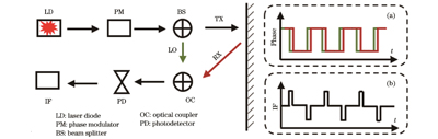
    Fig. 1. Schematic of working mechanism of PhMCW ranging lidar. Insets: (a) Lidar system; (b) IF signal
    Schematic of working mechanism of strict counting chain structure
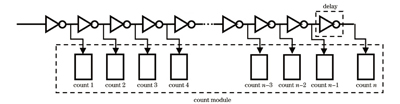
    Fig. 2. Schematic of working mechanism of strict counting chain structure
    Schematic of working mechanism of strict counting chain counter
    Fig. 3. Schematic of working mechanism of strict counting chain counter
    Schematic of TDC module design principle
    Fig. 4. Schematic of TDC module design principle
    Schematic of TDC performance test system
    Fig. 5. Schematic of TDC performance test system
    Measurement results of test signals. (a) 200 ns signal; (b) 1000 ns signal
    Fig. 6. Measurement results of test signals. (a) 200 ns signal; (b) 1000 ns signal
    Analysis of measurement results (pulse width of 6‒50 ns). (a) Test results with different pulse widths; (b) RMS
    Fig. 7. Analysis of measurement results (pulse width of 6‒50 ns). (a) Test results with different pulse widths; (b) RMS
    Analysis of measurement results (pulse width of 100‒1240 ns). (a) Test results with different pulse widths; (b) RMS
    Fig. 8. Analysis of measurement results (pulse width of 100‒1240 ns). (a) Test results with different pulse widths; (b) RMS
    Spectrogram analysis of measurement results. (a) Sampled data after processing by Hanning window function; (b) spectrum of measurement results
    Fig. 9. Spectrogram analysis of measurement results. (a) Sampled data after processing by Hanning window function; (b) spectrum of measurement results
    Test result of frequency of FPGA switching power supply
    Fig. 10. Test result of frequency of FPGA switching power supply
    Schematic diagram of lidar system
    Fig. 11. Schematic diagram of lidar system
    Analysis of lidar system measurement results. (a) Experimental results versus distance; (b) RMS versus distance
    Fig. 12. Analysis of lidar system measurement results. (a) Experimental results versus distance; (b) RMS versus distance
    Amplified standard pulsed signal captured by oscilloscope
    Fig. 13. Amplified standard pulsed signal captured by oscilloscope
    Huijuan Yu, Yubing Wang, Shuhua Zhao, Mingshi Zhang, Yue Song, Cheng Qiu, Yuxin Lei, Peng Jia, Lei Liang, Li Qin, Lijun Wang. Research on Automatic Driving Lidar Ranging Method Based on TDC[J]. Chinese Journal of Lasers, 2024, 51(8): 0810002
    Download Citation