• Advanced Photonics
  • Vol. 1, Issue 3, 034001 (2019)
Daniel J. Brod1, Ernesto F. Galvão1, Andrea Crespi2、3, Roberto Osellame2、3, Nicolò Spagnolo4、*, and Fabio Sciarrino4
Author Affiliations
  • 1Universidade Federal Fluminense, Instituto de Física, Niterói, Brazil
  • 2Consiglio Nazionale delle Ricerche, Istituto di Fotonica e Nanotecnologie, Milano, Italy
  • 3Politecnico di Milano, Dipartimento di Fisica, Milano, Italy
  • 4Sapienza Università di Roma, Dipartimento di Fisica, Roma, Italy
  • show less
    DOI: 10.1117/1.AP.1.3.034001 Cite this Article Set citation alerts
    Daniel J. Brod, Ernesto F. Galvão, Andrea Crespi, Roberto Osellame, Nicolò Spagnolo, Fabio Sciarrino. Photonic implementation of boson sampling: a review[J]. Advanced Photonics, 2019, 1(3): 034001 Copy Citation Text show less
    Boson sampling and its corresponding photonic implementation. (a) Conceptual scheme of the boson sampling task. The output probabilities after the scattering process are related to the evaluation of permanents of n×n submatrices of U, obtained by selecting rows and column of the matrix U describing the linear transformation. A classical simulation then requires the evaluation of hard-to-compute matrix permanents. (b) Photonic approach to building a quantum device that solves the boson sampling task. The three main building blocks are: (i) n photon sources for input state generation, (ii) m-mode linear interferometer, composed of beam splitters and phase shifters, implementing the selected unitary transformation U, and (iii) detectors on each of the output modes.
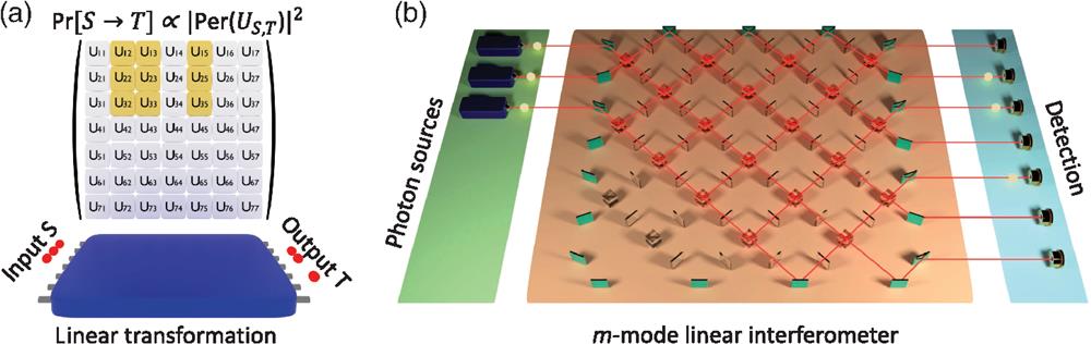
    Fig. 1. Boson sampling and its corresponding photonic implementation. (a) Conceptual scheme of the boson sampling task. The output probabilities after the scattering process are related to the evaluation of permanents of n×n submatrices of U, obtained by selecting rows and column of the matrix U describing the linear transformation. A classical simulation then requires the evaluation of hard-to-compute matrix permanents. (b) Photonic approach to building a quantum device that solves the boson sampling task. The three main building blocks are: (i) n photon sources for input state generation, (ii) m-mode linear interferometer, composed of beam splitters and phase shifters, implementing the selected unitary transformation U, and (iii) detectors on each of the output modes.
    Variants of the original boson sampling problem. (a) Scattershot boson sampling with multiple SPDC sources connected to the input ports of the interferometer. (b) Driven boson sampling, where layers of heralded sources are included between Haar-random unitaries to inject photons within the evolution. (c) Gaussian boson sampling, with multiple single-mode squeezers connected to the input ports of Haar-random unitaries. (d) Boson sampling with photon-added or photon-subtracted states, with variants also on the type of evolution (Haar-random or orthogonal matrices), and on the type of measurement (parity, on/off or photon-counting detection). (e) Multiboson correlation sampling (MBCS).
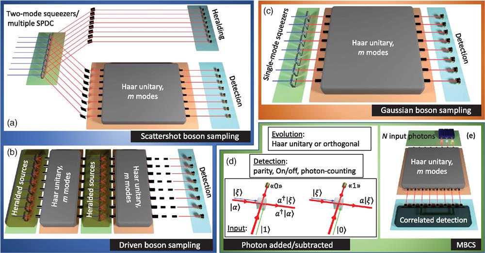
    Fig. 2. Variants of the original boson sampling problem. (a) Scattershot boson sampling with multiple SPDC sources connected to the input ports of the interferometer. (b) Driven boson sampling, where layers of heralded sources are included between Haar-random unitaries to inject photons within the evolution. (c) Gaussian boson sampling, with multiple single-mode squeezers connected to the input ports of Haar-random unitaries. (d) Boson sampling with photon-added or photon-subtracted states, with variants also on the type of evolution (Haar-random or orthogonal matrices), and on the type of measurement (parity, on/off or photon-counting detection). (e) Multiboson correlation sampling (MBCS).
    Experimental solutions, reported in the literature, to build photonic boson sampling machines. On the source side: (a) multiphoton generation from a single nonlinear crystal (NLC), (b) several two-photon generation processes to implement the scattershot boson-sampling, (c) integrated on-chip sources, (d) emission from semiconductor quantum dot. The unitary transformation is often implemented in the spatial modes using (e) multiport waveguide circuits composed of network of directional couplers, (f) micro-optic interferometers or (g) devices where several waveguides or fiber cores are continuously coupled. (h) The use of discrete time bins is also reported, exploiting fiber loops. Single photons are detected by (i) avalanche photo-diodes or (j) superconducting-nanowire detectors.
    Fig. 3. Experimental solutions, reported in the literature, to build photonic boson sampling machines. On the source side: (a) multiphoton generation from a single nonlinear crystal (NLC), (b) several two-photon generation processes to implement the scattershot boson-sampling, (c) integrated on-chip sources, (d) emission from semiconductor quantum dot. The unitary transformation is often implemented in the spatial modes using (e) multiport waveguide circuits composed of network of directional couplers, (f) micro-optic interferometers or (g) devices where several waveguides or fiber cores are continuously coupled. (h) The use of discrete time bins is also reported, exploiting fiber loops. Single photons are detected by (i) avalanche photo-diodes or (j) superconducting-nanowire detectors.
    Validation of boson sampling experiments. A sequence of tests is progressively performed on a data sample to exclude possible alternative scenarios. Experimental demonstrations with different approaches have shown the possibility of discriminating boson sampling data from the uniform distribution, the one obtained with distinguishable particles, and the mean-field sampler.
    Fig. 4. Validation of boson sampling experiments. A sequence of tests is progressively performed on a data sample to exclude possible alternative scenarios. Experimental demonstrations with different approaches have shown the possibility of discriminating boson sampling data from the uniform distribution, the one obtained with distinguishable particles, and the mean-field sampler.
    ExperimentnmSourceUnitary transformationDetector
    Broome et al.6336SPDCFiber splittersSPAD
    Spring et al.6436SPDCIntegrated optics (UV laser written)SPAD
    Tillmann et al.6535SPDCIntegrated optics (fs laser written)SPAD
    Crespi et al.6635SPDCIntegrated optics (fs laser written)SPAD
    Spagnolo et al.6539SPDCIntegrated optics (fs laser written)SPAD
    Carolan et al.6739SPDCIntegrated optics (SiOn)SPAD
    421Integrated optics (continuous coupling, SiN)
    Bentivegna et al.68313SPDC and SBSIntegrated optics (fs laser written)SPAD
    Carolan et al.6936SPDCIntegrated optics (reconfigurable, SiO2/Si)SPAD
    Loredo et al.7036Quantum dotFiber splittersSPAD
    He et al.7148Quantum dotFiber loops (time bin)SNSPD
    Wang et al.7259Quantum dotAssembled micro-opticsSPAD
    Wang et al.73516Quantum dotAssembled micro-opticsSNSPD
    Zhong et al.74512SPDC and SBSIntegrated optics (six modes) and polarizationSNSPD
    Paesani et al.75412SFWM, SBS, and GBSIntegrated optics (continuous coupling)SNSPD
    Table 1. Relevant details of the main photonic boson sampling experiments reported in the literature. Note: n is the maximum number of detected photons in the boson sampling experiment after unitary evolution; m is the number of available optical modes. SBS, scattershot boson sampling; GBS, Gaussian boson sampling.
    Daniel J. Brod, Ernesto F. Galvão, Andrea Crespi, Roberto Osellame, Nicolò Spagnolo, Fabio Sciarrino. Photonic implementation of boson sampling: a review[J]. Advanced Photonics, 2019, 1(3): 034001
    Download Citation