
Zhen Mou, Changda Zhou, Peiyao Lu, Qingyang Yue, Shuyun Wang, Shuyun Teng, "Structured vortices generated by metasurface holography," Photonics Res. 9, 2125 (2021)
- Photonics Research
- Vol. 9, Issue 10, 2125 (2021)
Abstract
1. INTRODUCTION
The optical vortex with nonuniform phase distribution and phase singularity has been an ongoing subject of concern in the past 30 years [1,2]. One typical vortex usually behaves as a helical phase wavefront and an annular intensity cross section [3,4]. One complex structured vortex, like the Laguerre–Gaussian (LG) beam [5], the Bessel–Gaussian (BG) beam [6], or the Mathieu beam [7], behaves with multiple-ring or multiple-spot intensity distribution, and the topological charges of the spiral phases in different regions may be same or different [8,9]. Because the vortex beam carries the orbital angular momentum, which provides the interaction of light and matter, it can be widely applied in optical tweezers [10], optical trapping [11], quantum communication [12], and quantum information processing [13]. The structured vortex with custom intensity and spiral phase distribution may expand to the wide applications in fields like 3D spiral fabrication [14,15].
A vortex beam may be generated by using many methods, such as the beam interference [16], forked grating [3], spatial light modulator [17], spiral slit [18,19], spiral phase plate [20], and metasurface [21,22]. In comparison with the other methods, metasurfaces can cause spatially varying optical responses through the interaction between the light field and nanostructure instead of spatial accumulation effect along an optical path [23]. Therefore, metasurfaces show the advantages of compact structure and powerful light manipulation and have attracted great interest. Flat optical devices, including metamirrors [24], metalenses [25,26], meta-axicons [27], metafilters [28], and metaholograms [29,30], have been proposed.
With the help of optical holography technology, metasurface holography can realize the record of the amplitude and phase of any object and the reproduction of the object using the metahologram [31–34]. Recently, some groups have reported the reproduction of designated intensity distribution or shaped wavefront. Ni
Sign up for Photonics Research TOC. Get the latest issue of Photonics Research delivered right to you!Sign up now
Besides the intensity modulation, wavefront shaping, and multiplexing image reproduction, as we know, the powerful light manipulation ability of metasurface holography is far more than above [38,39]. In this paper, we utilize metasurface holography to reproduce simultaneously the intensity pattern and phase distribution. We design a kind of structured vortex generator (SVG) using the designed metaholograms and obtain the structured vortices with multiple-ring intensity and a spiral phase. The topological charges of spiral phases in different radial regions may be same or different. The proposed SVG consists of rectangular holes etched in silver film. The structure information of SVG comes from a Fresnel hologram of the structured vortex field. Besides this fundamental design, the multiplexing metasurface SVG is also proposed to output the polarization controllable structured vortex. The reproduced results of structured vortices show our designed SVGs have low noise, high working efficiency, and large information capacity. The generation of a structured vortex and the design of a metasurface SVG will promote the applications of the metasurface holography and structured vortices in the fields of optical manipulation and integrated optics.
2. DESIGN PRINCIPLE
The structured vortex has the spatial distribution of multiple-ring intensity and a spiral wavefront. Two parameters of
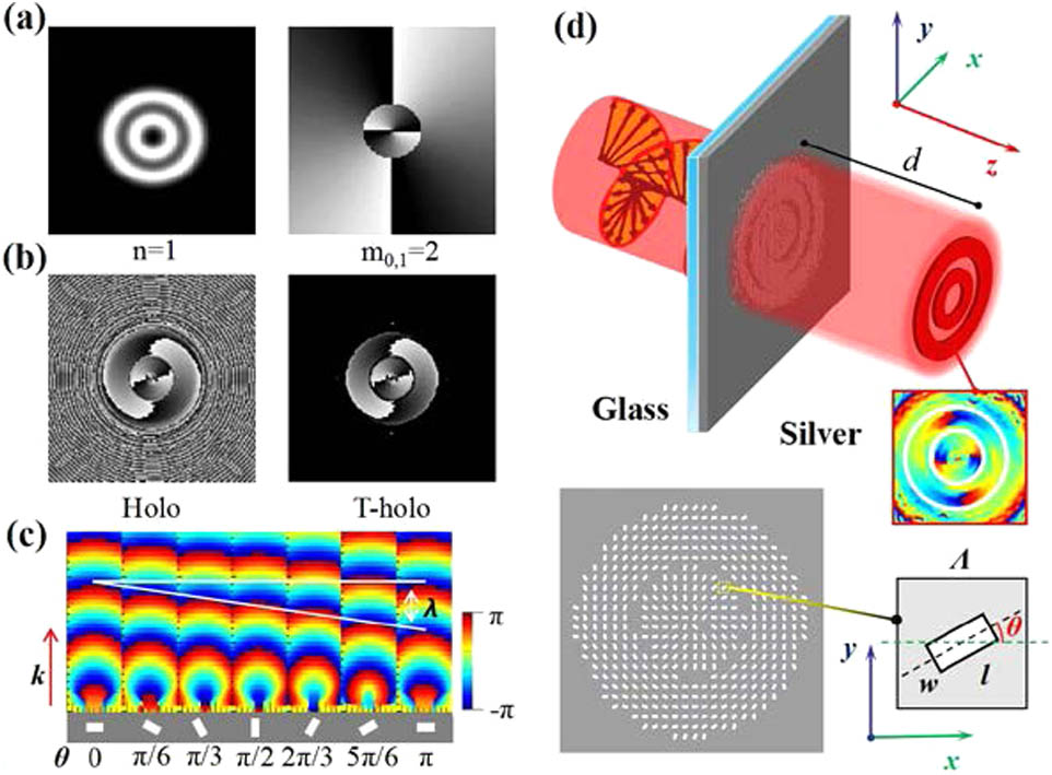
Figure 1.(a) Number of outer loops by
In order to generate this kind of structured vortex field using a metasurface, we construct the metahologram according to the Fresnel holography technique [40]. The structure information of the metahologram comes from the Fresnel transformation of the structured vortex field. Thus, we first construct the complex amplitude of the structured vortex field, which can be denoted by
In order to simplify the coding capacity of the Fresnel hologram, we set one or more threshold values according to the amplitude information, like the case of Fig. 1(b), where Holo and T-Holo denote the phase holograms without and with setting a threshold value, respectively. We can see that the spatial region of phase distribution gets smaller after setting a threshold value, which is more convenient for the design of the metasurface. In practice, we utilize the discrete rectangular nanoholes to construct the metahologram. The amplitudes and phases of the metahologram correspond to the data for the Fresnel hologram of
If one performs the inverse Fresnel transformation of
3. NUMERICAL SIMULATIONS
In order to increase optical performance of the designed SVG, we first optimize the parameters of the metasurface and ascertain the condition for the maximum transmittance of metasurface through the simulation calculations (see Appendix B). The thickness of the silver film deposited on the glass substrate takes 150 nm, and the length and width of the rectangular hole take
A. SVG Carrying the Same Topological Charge
This kind of SVG can generate the structured vortex fields where the topological charge of the vortex distributed in different radial regions is same. The gray-scale patterns at the left of Figs. 2(a) and 2(b) give the phase distributions of this kind of structured vortex; the parameter of
![]()
Figure 2.Intensity and phase distributions of the designed structured fields and the reproduced structured fields, where (a) the parameter of
In the designed structured vortex field, we perform a Fresnel transformation according to Eq. (1) and construct the corresponding metahologram according to the discretized data of Eq. (2). Then the reproduced image of the structured vortex field can be obtained with the right-handed circularly polarized light illumination. The color patterns at the right of Figs. 2(a) and 2(b) give the simulation results for the intensity and phase distributions of the reproduced light fields. In these two designs, the distance between the metasurface and the observation plane is set as
B. SVG Carrying Different Topological Charges
The optical vortex of the structured vortex field at different radial regions may have different topological charges. The second kind of SVG can generate this structured vortex field. The intensity and phase distribution characteristics of this kind of structured vortex can be seen from the patterns at the left of Figs. 2(c) and 2(d), where the parameter of
For these structured vortex fields, we perform the above-mentioned operation process and obtain their Fresnel metaholograms. We also set the distance between the metasurface and the observation plane at
C. Multiplexing SVG with Polarization Dependence
We also design a polarization-dependent SVG that can generate the different structured vortices with the illumination of the left-handed circularly polarized (LCP) light and right-handed circularly polarized (RCP) light. In order to realize the polarization control of the structured vortex field, we design one polarization multiplexing metasurface. We first obtain the Fresnel transformation of two structured vortex fields, as in the above operation. Then, we compare the amplitude information of the two Fresnel fields and construct one compound Fresnel field keeping only the information of the field with the greater amplitude. Setting a threshold value and rotating the rectangular nanoholes, the polarization multiplexing metasurface is formed.
Figures 3(a) and 3(c) give the combinations of the multiplexing structured vortex field, which includes two different structured vortex fields. One is the structured vortex field with the parameters of
![]()
Figure 3.Intensity and phase distributions of (a), (c) the designed structured vortex fields and (b), (d) the reproduced structured lights with different polarization light illuminations, where the parameter of
The color patterns of Figs. 3(b) and 3(d) show the intensity and phase distributions of the reproduced structured vortex fields generated by the same metahologram with the LCP and RCP light illumination. From the simulation results, we can see one bright ring appears with the RCP light illumination, and two bright rings are produced with the LCP light illumination. The phase for the former changes two times
It is interesting that the phase distribution with the opposite topological charge appears when the designed SVG is illuminated by the orthogonal circularly polarized light. As shown in the dark areas in Figs. 3(b) and 3(d), although the intensity of the bright ring disappears under the orthogonal circularly polarized light illumination, the phase changing in the opposite direction can still be seen. We think this is because the SVG is designed on the basis of the geometric phase which is being carried by the cross polarization, and the designed SVG is similar to the spiral phase plate.
Similarly, any structured light field can be generated by building the model of the structured light field and constructing the appropriate metahologram, although only three kinds of SVGs are provided in this paper. Furthermore, it needs to be pointed out that the determination of metasurface parameters, the realization of the metahologram, the simulations for the wavefront of single rectangular nanohole, and the reproduction of the metahologram are completed by using the finite-difference time-domain technique (see Appendix C).
4. EXPERIMENT MEASUREMENT
A practical experiment is performed to verify the performance of our proposed metasurface SVG. We manufacture one sample of the polarization-dependent SVG; Fig. 4(b) gives the scanning electron microscope (SEM) image and a part of its magnified image. During the manufacture of the sample, a silver film with the thickness of 150 nm is deposited on the glass substrate by using the magnetron sputtering method, and the rectangular nanoholes are fabricated by means of the focused ion beam etching method. We put the sample of SVG into the optical path shown in Fig. 4(a) and measure its reproduced image. The linearly polarized light emitted from the He–Ne laser changes into the RCP and LCP light with the help of a polaroid (
![]()
Figure 4.(a) Experiment setup for measuring the diffraction intensity and phase distributions of the SVG sample; (b) SEM image of the SVG sample, where the inserted patterns at the bottom are the magnified part; (c) and (d) the measured diffraction intensity distributions under RCP and LCP light illumination; and (e) and (f) the interference results of the reproduced vortex fields and the plane wave for two illumination conditions, where the wavelength of the illuminating light takes 632.8 nm.
From Figs. 4(c) and 4(d), one can see that one bright ring appears with the RCP light illumination and two bright rings appear with the LCP light illumination. These are the same as the simulated results of Figs. 3(b) and 3(d). From the interference results in Figs. 4(e) and 4(f), one can observe many bright spots with respect to the positions of the bright rings. For convenient comparison, we label their positions near these bright spots by the short dashed lines. The numbers of the bright spots for two symmetric parts of any ring are also marked out. It is easy to see that the difference of bright spots at two symmetric parts in Fig. 4(e) is 2, which corresponds to the value of the parameter of
5. CONCLUSIONS
In summary, we designed metasurface SVGs on the basis of metasurface holography. Our proposed metasurface SVGs consist of rectangular nanoholes, and they modulate the amplitude and phase of light fields to generate the structured vortex lights. Three kinds of metasurface SVGs are created: an SVG with the same topological charge, an SVG with different topological charges, and a polarization multiplexing SVG. The simulation and experiment results show the reproduced images of the structured vortex fields can appear as expected. The generation of the structured vortices can realize the parallel output of several vortices, which can be applied in optical manipulation, including particle screening and trapping with many channels, and the polarization multiplexing SVG can also be utilized with flexible control. The advantages of the metasurface, including the ultrathin structure, flexible control, large information capacity, and easy integration, offer the proposed SVGs more potential applications, from high-resolution imaging and micromanipulation to quantum communication.
APPENDIX A: MODEL OF STRUCTURED VORTEX
One structured vortex field
The amplitude and phase information can be recorded based on optical holography technology, and the image of the object can be reproduced under the reference light illumination. After ascertaining the parameters of the structured vortex, we perform the Fresnel transformation, and the transformed field can be written as Eq. (
Obviously, it is just the target function of
APPENDIX B: OPTIMIZATION OF METASURFACE
The sampling interval or the information content is the key issue for image reproduction. In terms of the Nyquist sampling theorem, when the propagation distance
While the incident light takes the RCP, the transmitted polarization state of nanohole in the circular base can be expressed by [
Though the polarization conversion efficiency of this nanohole is not too high, the parameters for the rectangular hole are the optimization results after considering comprehensively the transmission intensity, the sampling points, and the polarization conversion.
APPENDIX C: SIMULATION METHOD
The realization of the metahologram, the determination of metasurface parameters, and the simulated diffraction distributions are obtained by using the finite-difference time-domain technique. In practical simulation calculations, the perfectly matched layers are used as the boundaries to prevent nonphysical scattering; the minimum mesh step is set at 2 nm. The RCP light is chosen as the illuminating light for the results in Figs.
During the determination of the metasurface parameters, the calculation conditions are chosen as the detection plane at 2 μm away from the nanohole etched on the silver film, with the length and width of the rectangular nanohole swept from 0 to 150 nm, with a step of 5 nm. For realization of the metahologram, the positions of nanoholes are located on the sampling points of the Fresnel hologram. The construction of the metahologram model is finished according to the written script and the default parameters.
We set the corresponding parameters of the calculation phenomenon, including the thickness of the silver film, the length and width of the nanohole, the intervals of two adjacent nanoholes along two orthogonal directions, the rotation angle of the nanohole at any point, the illumination condition, and the monitor plane of the reproduced image. Thus, the intensity and phase distributions are calculated based on the iteration rule of electromagnetic fields. Many simulated calculations with respect to different metaholograms provide the solid foundation for the design of the practical metaholograms.
References
[1] P. Coullet, L. Gil, F. Rocca. Optical vortices. Opt. Commun., 73, 403-408(1989).
[2] Y. Shen, X. Wang, Z. Xie, C. Min, X. Yuan. Optical vortices 30 years on: OAM manipulation from topological charge to multiple singularities. Light Sci. Appl., 8, 90(2019).
[3] M. Padgett, J. Courtial, L. Allen. Light’s orbital angular momentum. Phys. Today, 57, 35-40(2004).
[4] X. Cai, J. Wang, M. J. Strain, B. Johnson-Morris, J. Zhu, M. Sorel, J. L. O’Brien, M. G. Thompson, S. Yu. Integrated compact optical vortex beam emitters. Science, 338, 363-366(2012).
[5] S. Haddadi, O. Bouzid, M. Fromager, K. Hasnaoui, A. Harfouche, E. Cagniot, A. Forbes, K. Ait-Ameur. Structured Laguerre-Gaussian beams for mitigation of spherical aberration in tightly focused regimes. J. Opt., 20, 045602(2018).
[6] K. Zhu, G. Zhou, X. Li, X. Zheng, H. Tang. Propagation of Bessel-Gaussian beams with optical vortices in turbulent atmosphere. Opt. Express, 16, 21315-21320(2008).
[7] Y. Zhang, X. Yang, J. Gao. Generation of nondiffracting vector beams with ring-shaped plasmonic metasurfaces. Phys. Rev. Appl., 11, 064059(2019).
[8] Y. Yang, G. Thirunavukkarasu, M. Babiker, J. Yuan. Orbital-angular-momentum mode selection by rotationally symmetric superposition of chiral states with application to electron vortex beams. Phys. Rev. Lett., 119, 094802(2017).
[9] S. Mei, M. Q. Mehmood, S. Hussain, K. Huang, X. Ling, S. Y. Siew, H. Liu, J. Teng, A. Danner, C. W. Qiu. Flat helical nanosieves. Adv. Funct. Mater., 26, 5255-5262(2016).
[10] D. G. Grier. A revolution in optical manipulation. Nature, 424, 810-816(2003).
[11] C. Liberale, P. Minzioni, F. Bragheri, F. De Angelis, E. Di Fabrizio, I. Cristiani. Miniaturized all-fibre probe for three-dimensional optical trapping and manipulation. Nat. Photonics, 1, 723-727(2007).
[12] M. Mirhosseini, O. S. Magaa-Loaiza, M. N. O’Sullivan, B. Rodenburg, M. Malik, M. P. J. Lavery, M. J. Padgett, D. J. Gauthier, R. W. Boyd. High-dimensional quantum cryptography with twisted light. New J. Phys., 17, 033033(2014).
[13] Z. Q. Zhou, Y. L. Hua, X. Liu, G. Chen, J. S. Xu, Y. J. Han, C. F. Li, G. C. Guo. Quantum storage of three-dimensional orbital-angular-momentum entanglement in a crystal. Phys. Rev. Lett., 115, 070502(2014).
[14] J. Ni, Y. Hu, S. Liu, Z. Lao, S. Ji, D. Pan, C. Zhang, B. Xu, J. Li, D. Wu, J. Chu. Controllable double-helical microstructures by photonic orbital angular momentum for chiroptical response. Opt. Lett., 46, 1401-1404(2021).
[15] J. Ni, C. Wang, C. Zhang, Y. Hu, L. Yang, Z. Lao, B. Xu, J. Li, D. Wu, J. Chu. Three-dimensional chiral microstructures fabricated by structured optical vortices in isotropic material. Light Sci. Appl., 6, e17011(2017).
[16] A. Kapoor, M. Kumar, P. Senthilkumaran, J. Joseph. Optical vortex array in spatially varying lattice. Opt. Commun., 365, 99-102(2016).
[17] Y. Ohtake, T. Ando, N. Fukuchi, N. Matsumoto, T. Hara. Universal generation of higher-order multiringed Laguerre-Gaussian beams by using a spatial light modulator. Opt. Lett., 32, 1411-1413(2007).
[18] H. Wang, L. Liu, C. Zhou, J. Xu, M. Zhang, S. Teng, Y. Cai. Vortex beam generation with variable topological charge based on a spiral slit. Nanophotonics, 8, 317-324(2019).
[19] C. Zhou, M. Zhen, Z. Li, S. Teng. Compound plasmonic vortex generation based on spiral nanoslits. Front. Phys., 16, 33503(2021).
[20] M. W. Beijersbergen, R. P. C. Coerwinkel, M. Kristensen, J. P. Woerdman. Helical-wavefront laser beams produced with a spiral phase plate. Opt. Commun., 112, 321-327(1994).
[21] E. Karimi, S. A. Schulz, I. De Leon, H. Qassim, J. Upham, R. W. Boyd. Generating optical orbital angular momentum at visible wavelengths using a plasmonic metasurface. Light Sci. Appl., 3, e167(2014).
[22] H. Wang, L. Liu, X. Lu, H. Lv, Y. Han, S. Wang, S. Teng. Spatial multiplexing plasmonic metalenses based on nanometer cross holes. New J. Phys., 20, 123009(2018).
[23] N. Yu, F. Capasso. Flat optics with designer metasurfaces. Nat. Mater., 13, 3839(2014).
[24] S. Boroviks, R. A. Deshpande, N. A. Mortensen, S. I. Bozhevolnyi. Multifunctional meta-mirror: polarization splitting and focusing. ACS Photon., 5, 1648-1653(2017).
[25] B. Groever, W. T. Chen, F. Capasso. Meta-lens doublet in the visible. Nano Lett., 17, 4902-4907(2017).
[26] H. Lv, X. Lu, Y. Han, Z. Mou, S. Teng. Multifocal metalens with a controllable intensity ratio. Opt. Lett., 44, 2518-2521(2019).
[27] R. Bao, Z. Mou, C. Zhou, Q. Bai, X. He, Z. Han, S. Wang, S. Teng. Generation of diffraction-free beams using resonant metasurfaces. New J. Phys., 22, 103064(2020).
[28] L. Liu, H. Wang, Y. Han, X. Lu, H. Lv, S. Teng. Color filtering and displaying based on hole array. Opt. Commun., 436, 96-100(2019).
[29] G. Zheng, H. Muhlenbernd, M. Kenney, G. Li, T. Zentgraf, S. Zhang. Metasurface holograms reaching 80% efficiency. Nat. Nanotechnol., 10, 308-312(2015).
[30] L. Huang, X. Chen, H. Mühlenbernd, Z. Hao, S. Chen, B. Bai, Q. Tan, G. Jin, K. W. Cheah, C. W. Qiu, J. Li, T. Zentgraf, S. Zhang. Three-dimensional optical holography using a plasmonic metasurface. Nat. Commun., 4, 2808(2013).
[31] L. Huang, S. Zhang, T. Zentgraf. Metasurface holography: from fundamentals to applications. Nanophotonics, 7, 1169-1190(2018).
[32] Z. L. Deng, G. Li. Metasurface optical holography. Mater. Today Phys., 3, 16-32(2017).
[33] W. Wan, G. Jie, X. Yang. Metasurface holograms for holographic imaging. Adv. Opt. Mater., 5, 1700541(2017).
[34] Q. Jiang, G. Jin, L. Cao. When metasurface meets hologram: principle and advances. Adv. Opt. Photon., 11, 518-576(2019).
[35] X. Ni, A. V. Kildishev, V. M. Shalaev. Metasurface holograms for visible light. Nat. Commun., 4, 2807(2013).
[36] I. Dolev, I. Epstein, A. Arie. Surface-plasmon holographic beam shaping. Phys. Rev. Lett., 109, 203903(2012).
[37] J. P. Balthasar Mueller, N. A. Rubin, R. C. Devlin, B. Groever, F. Capasso. Metasurface polarization optics: independent phase control of arbitrary orthogonal states of polarization. Phys. Rev. Lett., 118, 113901(2017).
[38] Z. Jin, S. Mei, S. Chen, Y. Li, C. Zhang, Y. He, X. Yu, C. Yu, J. K. W. Yang, B. Luk’yanchuk, C. W. Qiu. Complex inverse design of meta-optics by segmented hierarchical evolutionary algorithm. ACS Nano., 13, 821-829(2019).
[39] L. Jin, Y. W. Huang, Z. Jin, R. C. Devlin, Z. Dong, S. Mei, M. Jiang, W. T. Chen, Z. Wei, H. Liu, J. Teng, A. Danner, X. Li, S. Xiao, S. Zhang, C. Yu, J. K. W. Yang, F. Capasso, C. W. Qiu. Dielectric multi-momentum meta-transformer in the visible. Nat. Commun., 10, 4789(2019).
[40] Z. Mou, X. Lu, H. Lv, Y. Han, S. Teng. Metasurface array illuminator based on Fresnel holography. Opt. Lasers Eng., 131, 106146(2020).
[41] E. Hasman, V. Kleiner, G. Biener, A. Niv. Polarization dependent focusing lens by use of quantized Pancharatnam–Berry phase diffractive optics. Appl. Phys. Lett., 82, 328(2003).
[42] S. Y. Teng, Q. Zhang, H. Wang, L. X. Liu, H. R. Lv. Conversion between polarization states based on a metasurface. Photon. Res., 7, 246-250(2019).
[43] E. D. Palik. Handbook of Optical Constants of Solids(1985).


Set citation alerts for the article
Please enter your email address

© Copyright 2018-2021 | Chinese Laser Press. All Rights Reserved 沪ICP备15018463号-20