
Jue Wang, Chengkun Cai, Tianhao Fu, Kangrui Wang, Yize Liang, Jian Wang. Ultracompact phase plate fabricated by femtosecond laser two-photon polymerization for generation of Mathieu--Gauss beams[J]. Advanced Photonics Nexus, 2023, 2(1): 016011
- Advanced Photonics Nexus
- Vol. 2, Issue 1, 016011 (2023)
Abstract
Keywords
1 Introduction
The concept of nondiffracting beams was first brought up by Durnin in 1987.1 He presented exact solutions to the homogeneous Helmholtz equation that were not subject to diffraction. Since then, light with propagation invariance has been a focus of attention for researchers. The Mathieu beam is the solution of the Helmholtz equation based on its separability in elliptical cylindrical coordinates.2 Like other nondiffracting beams, the Mathieu beam is featured by its nondiffraction,3 self-reconstruction,4 and self-acceleration.5 Different from its relatives, for example, the Bessel beam, cosine beam, and parabolic beam,6 the transverse intensity of Mathieu beams are lattice-like, which is proper for scientific use. Because of the properties above, scientists have used the Mathieu beam in many fields, including photonic lattices,7 optical trapping,8 speckle phenomena,9 and laser processing.10,11
For further applications of Mathieu beams, the generation of Mathieu beams with high quality is necessary. Several efforts have been made to produce Mathieu beams in the experiment. The first experimental demonstration of the Mathieu beam was reported by Gutiérrez-Vega et al.12 After that, many methods emerged to generate such beams. The hologram method can produce high-order Mathieu beams, but the generated beams are of poor quality due to manufacturing errors.13 In addition, spatial light modulators (SLMs) are widely used to generate Mathieu beams.3,4,10,14 However, the inherent nature of the relatively large pixel size and spacing makes it hard to produce high-quality Mathieu beams. In addition, the relatively large size of SLM makes it hard to apply the Mathieu beam in an integrated optical system. Recently, more compact devices based on metasurfaces15,16 have emerged. Ring-shaped plasmonic metasurfaces have been proposed to yield Mathieu beams with high quality.17 Generally speaking, the metasurface is a method of pixelization. The size of the pixel is about . Also, it is based on processes, such as the focused ion beam and electron beam lithography, which are suitable for 2D patterning. Femtosecond laser two-photon polymerization (TPP) has emerged as a new micronanoprocessing technology, which is the way to produce sophisticated three-dimensional (3D) structures with an accuracy of up to 100 nm.18
In this work, using femtosecond laser TPP, we propose and demonstrate the fabrication of even and helical Mathieu phase plates (MPPs) with different orders and ellipticity parameters in a miniature size (). Compared with traditional methods, the MPPs fabricated here can realize an ultracompact size while maintaining high accuracy that brings about high beam quality. Our study may provide new possibilities for miniature applications of nondiffracting beams in optical communications, particle manipulation, and material processing.
Sign up for Advanced Photonics Nexus TOC. Get the latest issue of Advanced Photonics Nexus delivered right to you!Sign up now
2 Design and Fabrication
The ideal Mathieu beams are described in cylindrical elliptical coordinates . The cylindrical elliptical coordinates can be transformed into Cartesian coordinates as
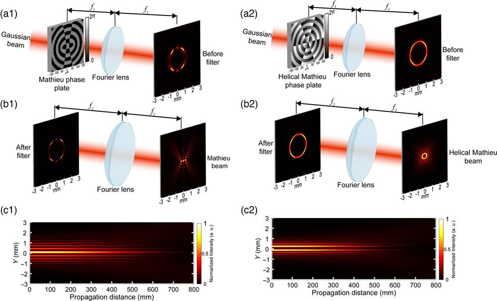
Unlike ideal Mathieu beams, which cannot be realized experimentally due to their infinite energy, the Mathieu–Gauss (MG) beams can be generated in the lab, carrying finite energy and being diffraction-free in the finite region. To generate such beams, we follow the method: the MG beam is converted from a Gaussian beam imposed by an ideal Mathieu phase passing through the 4-f system filtering. Figure 1 shows the schematics of the method for generating the even MG beam with and [Figs. 1(a1)–1(c1)] and helical MG beam with and [Figs. 1(a2)–1(c2)]. In our simulation, focus distance c is set to 50 and 19 μm for even and helical cases.
![]()
Figure 1.Schematics of the method for generating (a1)–(c1) even and (a2)–(c2) helical Mathieu beams. (a1) and (a2) Generation of ring-shaped Fourier spectra through Fourier transformation of a Gaussian beam imposed with an MPP. (b1) and (b2) Generation of a Mathieu beam through Fourier transformation of Fourier spectra after the filter. (c1) and (c2) Simulation of intensity distribution along the propagation axis.
We take the generation of even MG beam as an example. As can be seen in Fig. 1(a1), when a 1550 nm Gaussian beam embedded with the Mathieu phase is transformed by a lens (focal length ), a ring-shaped Fourier spectra is generated. The unfiltered Fourier spectra consists of several rings surrounding the main ring. Compared with it, the spectra of the ideal Mathieu beam has only one main ring with an infinitely small ring width. Note that the radius of the main ring is dependent on and its width is related to the Gaussian envelope.6 The radius and width of the main ring can be calculated as
![]()
Figure 2.(a) and (b) Femtosecond laser platform for TPP. (c) Phase distribution of designed even MPP with
A femtosecond laser TPP platform is used to fabricate MPPs, which is shown in Fig. 2(a). A femtosecond laser (PHAROS, 200-kHz repetition rate, 515-nm wavelength, and 340-fs pulse width) focused by an oil immersion objective (Zeiss, , 1.4 NA) induces TPP in the photoresist SZ-2080. The 3D translation stages are used to control the relative position of laser foci. In another path, the light from an LED propagated through the mirror, beam splitter, dichroic mirror, and the objective illuminate the fabricated sample. The sample image is captured by the CCD. The detailed schematic of fabrication can be seen in Fig. 2(b), where index-matching oil and photoresist are deposited on both sides of the glass substrate. Note that one droplet of photoresist is dropped on the glass substrate and then prebacks at 100 °C for 30 min before fabrication.
The femtosecond laser TPP can easily convert the phase information to the height profile. For the wavelength of incident light and refractive index of photoresist , the relationship between the height and the phase distribution is expressed as
Figure 2(c) shows the even MPP with and that we designed. Compared to the one in Fig. 1(a), it adds a margin of phase zero. The height profile of the designed MPP is depicted in Fig. 2(f) for and , where the binary phases of 0 and correspond to the height of 0 and . A layer-by-layer scanning method is used to fabricate the structure we designed. After the laser-induced polymerization, the sample is developed in methyl isobutyl ketone for 10 min to remove the residue and then is bathed in isopropanol for 5 min. We integrate multiple MPPs on a single substrate, shown in Fig. 2(d). One of the MPPs with and is characterized by scanning electron microscopy (SEM), shown in Fig. 2(e). To characterize its height profile quantitatively, we use a 3D laser scanning confocal microscope (VK-X1100, KEYENCE) to measure the fabricated MPP. The surface profile of the fabricated MPP [Fig. 2(g)] is in agreement with the designed one [Fig. 2(f)]. To facilitate visualization, we scale up the height by 20 times in Figs. 2(f) and 2(g). The color bar in the contour image shows an error of around caused by the fabrication process, which would impair the quality of generated beams. However, further experimental characterization of the MG beams indicates that such a slight error has little effect on the quality of the resulting MG beams.
Except for the even MPP with a binary phase distribution, we also fabricate helical MPPs with a vortex wavefront. Figure 3(a) plots the phase distribution of a helical MPP with and . As can be seen, it possesses multiple concentric rings with a helical wavefront. The fabricated helical MPP is characterized using SEM, which is shown in Fig. 3(b). Its height profile is measured quantitatively, depicted in Fig. 3(c). To facilitate visualization, we scale up the height by 5 times.
![]()
Figure 3.Helical MPP with
We can see from Figs. 2(g) and 3(c) that the fabricated even and helical MPPs have height errors. These errors will further affect the phase modulation, which may degrade beam quality. Regarding fabrication level, there are two types of errors when we neglect the translation system error. One is the overall height error that is caused by differences between the designed and practical wavelength or refractive index of photoresist , according to Eq. (4). In this case, the overall phase modulation will be scaled proportionally, as depicted in Fig. 4(a). In the figure, the binary phase is not ideal 0 and , but 0 and . Another error is caused by the layer-by-layer fabrication method of TPP. In practice, the spacing between layers is not infinitely small. So there are always existing steps when fabricating a continuous phase plate, just as in Fig. 3(c). In this case, the phase modulation is also discretized, as shown in Fig. 4(b).
![]()
Figure 4.(a) Phase distribution of even MPP with phase modulation error. (b) Phase distribution of helical MPP with discretized phase values of 31 levels. The overlap integral and efficiency of (c) even and (d) helical Mathieu beams at different phase modulations. Marks denote the value when the phase value is discretized into 31 levels. The bars on the marks show the deviation of the value caused by levels of phase value discretization.
We analyze how these modulation errors affect the beam quality for both even and helical cases, as presented in Figs. 4(c) and 4(d). Here, we use overlap integral to measure the similarity between ideal and practical beams. The efficiency is used to measure the energy loss of the produced beams.
In Figs. 4(c) and 4(d), the red circles and orange cubics denote overlap integral and efficiency, respectively, when the phase value is discretized into 31 levels corresponding to our fabrication. Here, the bar on the mark indicates the deviation of overlap integral and efficiency, which is caused by different levels of discretized phase values. We simulate the situation of ideal phase distribution and discretized phase values of 15 levels.
In the case of 31 levels of phase values (see marks), we can see in Fig. 4(c) that the overlap integral of the even Mathieu beam is above 99.5% with different phase modulations. The beam efficiency increases with the increase of phase modulation when it is less than . After that, the efficiency decreases slowly. In Fig. 4(d), the overlap integral and efficiency have the same trend. They reach the highest value when the phase modulation is around . It is counterintuitive that the highest value does not appear in the phase modulation of . It is because the discretized phase values make optimal overlap integral and efficiency deviated. When considering the ideal phase distribution without discretization, the upper limit of efficiency and overlap integral in both even and helical cases reach the peak value when the phase modulation is the ideal . Also, we plot the intensity distribution of Mathieu beams at phase modulation of , , and for both cases.
3 Characterization of the MG Beams
The experimental setup for generating and characterizing even MG beams is depicted in Fig. 5. With the help of the 4-f system, the collimated laser beam is transformed into MG beams of even parity. The beam expander is used to narrow the laser beam illuminating the MPPs. Lens 1 and Lens 2, with different focal lengths (30 and 300 mm, respectively), are used to enlarge the generated MG beams so that the CCD can fully record. The right-angle prism (RAP) mounted on a translation stage is used as an optical delay. It enables us to measure the intensity distribution of MG beams along the optical axis.
![]()
Figure 5.Experimental setup for the generation and characterization of MG beams. BE, beam expander; L1 and L2, lenses; RS, ring slit; M, mirror; and RAP, right-angle prism.
We design and fabricate the even MPPs with different orders (, 1, 2) and ellipticity parameters (, 24, 36). The intensity distributions of beams at the Fourier plane are measured, as shown in Fig. 6. We can see that bright centers exist in the Fourier spectra compared to our simulation in Fig. 1(a1). This is because the beam illuminating the MPPs is slightly oversized. The beam that exceeds the MPPs will be transformed into a low-frequency component in Fourier spectra. After filtering at the back focal plane of Lens 1, the MG beams are reconstructed at the back focal plane of Lens 2. The generated even MG beams with different and are demonstrated in Fig. 7. They are similar to the ideal even MG beams described by Eq. (2). We also measure the energy efficiency of the produced even MG beam with and , whose energy efficiency is about 40%. It is slightly lower than the simulated value of 54.5% because of the additional loss caused by the input Gaussian beam beyond the range of MPPs.
![]()
Figure 6.Measured Fourier spectra of MG beams with different orders
![]()
Figure 7.Measured intensity distribution of even MG beams with different orders
To further test the propagation invariance of the resulting MG beams, we take the even MPP with and as an example, measuring its intensity distributions at different propagation distances. The measured results are shown in Fig. 8(a), where we record from to ( refers to the back focal plane of Lens 2). In addition, the axial intensity distribution of the propagating beam is measured and plotted in Fig. 8(b). It shows that the generated MG beam is approximately diffraction-free within 800 mm.
![]()
Figure 8.Experimental results of even MG beams with
We present experimental results of helical MG beams with different parameters and , as shown in Fig. 9. The elliptical rings are obtained when normalized coefficients and are equal.25 It can be seen that with the increase in order , the eccentricity of the innermost ring increases. In addition, to verify the nondiffracting property of the helical MG beams, we experimentally present the helical MG beam with and . Figure 10(a) plots the transverse intensity distribution of helical MG beam at different propagation distances from to . Moreover, the corresponding axial intensity distribution along the propagation is recorded, as depicted in Fig. 10(b). The results show characteristics of propagation invariance of the helical MG beam within 800 mm.
![]()
Figure 9.Measured intensity distribution of helical MG beams with different
![]()
Figure 10.Experimental results of helical MG beams with
The obtained results in Figs. 6–10 indicate the successful generation of even and helical Mathieu beams with impressive performance. The TPP-based MPPs that we fabricated have a compact size of with 100-nm spatial accuracy. These generated Mathieu beams with high quality can be applied to the cutting-edge research field and areas where there is a need for device miniaturization.
4 Conclusion
In summary, we have proposed, designed, and fabricated even and helical MPPs. The femtosecond laser TPP process has been utilized to fabricate MPPs with high accuracy, proving its ability in nanofabrication with rapidity and flexibility. The MG beams with high quality have been experimentally demonstrated using the MPPs. Also, their diffraction-free characteristics have been verified. Our method can achieve even more compact MPPs with micrometer size, which may facilitate future miniature applications of nondiffracting beams in optical communications, optical trapping, laser processing, and more.
Biographies of the authors are not available.

Set citation alerts for the article
Please enter your email address
© Copyright 2018-2021 | Chinese Laser Press. All Rights Reserved 沪ICP备15018463号-20