Yang Yu, Shangyuan Li, Xiaoping Zheng, Hanyi Zhang, Bingkun Zhou. Sidelobe suppression analysis of microwave photonic filter based on spectrum-shaped optical frequency combs[J]. Chinese Optics Letters, 2016, 14(6): 060601
Copy Citation Text
A finite impulse-response microwave photonic filter is typically achieved based on spectrum-shaped optical frequency combs and a dispersive element. We propose an analytical model to describe the amplitude responses of the sidelobes. The model shows that the sidelobe suppression ratio is limited by the spectrum structure of the optical combs. By taking Gaussian-profiled combs as an example, it is both theoretically and experimentally proved that the suppression ratio can be improved by optimizing the spectral power range, which is defined as the ratio of the maximum tap weight to the minimum tap weight.
Microwave photonic filters (MPFs) have the advantages of a wide band, tunability, and reconfigurability to filtering work in application fields, such as in radar systems, wireless communication, and radio astronomy[1]. A filter with high main-to-sidelobe suppression ratio (MSSR) is required in these applications. The MSSR is the ratio of the mainlobe gain in decibels relative to the gain of the largest sidelobe. A high suppression ratio is significant in attenuating undesired noise and clutters[2].
Several MPF approaches[3–11] have been proposed, such as the recirculating delay lines method, which has a high frequency selectivity but a poor tunability[3], and the stimulated Brillouin scattering method, which has a frequency response that changes with the power of the input signal[4]. The most researched approach is the finite impulse-response (FIR) MPF[1,2,5]. A multiple carrier optical source is used to carry the radio frequency (RF) signal via an electro-optical modulator. The optical signal is then time delayed according to the wavelength via a dispersive medium, and finally, it is fed into a photodiode (PD) to regenerate the RF signal. Each optical carrier stands for a tap. The quality factor (), which is the frequency-to-bandwidth ratio of the filter, can be approximated by the number of taps[2]. The multiple carrier optical source can be implemented by using laser arrays[5], sliced broadband optical sources (BOSs)[6–8], and optical frequency combs (OFCs)[9–11]. However, when using laser arrays as the optical source, the number of tap weights is too expensive to expand, such that the value is very low. When using a BOS, the filtered signal is worsened with noise[12,13]. The approaches based on OFCs are most widely investigated because it is easy to enlarge the number of wavelengths to improve the filter’s spectral selectivity. For example, self-phase modulation spectrum broadening was used to obtain 365 combs and achieved a filter with a value of 296[9].
The frequency response of the FIR MPF depends on the optical spectra of multiple carrier optical sources. For instance, an MPF was demonstrated by using a specially designed multi-wavelength ring laser, which is equivalent to a 23-point Hamming window[10]. The MSSR is only 25 dB. Therefore, an optical spectrum processor (OSP)[14,15] is usually used to shape the spectra to improve the MSSR. The work in Ref. [11] used a line-by-line pulse shaper to manipulate the optical power of combs to achieve the spectra with Gaussian profile and finally achieved an MSSR of only 35 dB. In our previous work[16], we demonstrated an MPF with a high MSSR and discussed the influence of shaping precision on the MSSR. However, the relationship between the MSSR and the spectrum structure is still unclear. The power range of the spectra is an intrinsic property of the spectral structure. It is an important problem to find a value of the MSSR that is as high as possible under the limitation of the power range.
Sign up for Chinese Optics Letters TOC. Get the latest issue of Chinese Optics Letters delivered right to you!Sign up now
In this Letter, we demonstrate an analysis of the relationship between the spectrum structure of the OFC and the transfer function of the FIR MPF based on dispersion delay. The level of these sidelobes is restricted by the spectral power range (SPR). Then, we take a Gaussian-shaped spectrum as an example to show that the MSSR can be enhanced by optimizing the SPR.
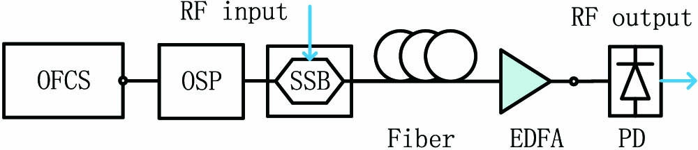
The schematic diagram of a typical FIR MPF is illustrated in Fig. 1. The optical combs from the OFC source is firstly manipulated by an OSP that can be programmed to control the optical power of each comb. After shaping, the OFC is single-sideband (SSB) modulated with the RF signal. The SSB modulation is used to combat fiber dispersion-induced power fading[17]. The optical fiber works as a dispersive element to provide an equally spaced differential group delay between adjacent wavelengths. Because the higher-order dispersion is very small and its influence can be ignored[1,7], the dispersion element can be described by where is the total second-order dispersion[11]. After being cascaded with an erbium-doped fiber amplifier (EDFA), the light is finally fed into a PD.
The transfer function of the MPF depends on the optical power of all the combs. The frequency domain representation of the frequency combs is a series of delta functions with the comb tooth spacing . The number of comb lines is . If is the offset angular frequency, the angular frequency of the nth comb is . Thus, the electric field in the time domain can be written as where and are the optical intensity and phase of the nth comb line, respectively.
After modulation, the nth optical carrier is time delayed by . According to Ref. [11], the transfer function for the MPF is the sum of these delayed signals, and it can be written as where is the angular frequency of the RF signal, and is just a coefficient depending on the half-wave voltage of the modulator, the responsivity of the PD, the gain of the optical link, and the load impedance[18]. The filter has a periodic amplitude response. The free spectral range (FSR) of the transfer function is .
In order to simplify Eq. (3), we can use the following lemma. Assuming is a continuous function and is large enough, the sum of the alternating series can be written as where is the big notation.
Around the center of the stopband of the transfer function, is close to . In this way, we can use Eq. (4) to obtain which can describe the level of sidelobes in the center of the transfer function. Moreover, ignoring the coefficient , the largest sidelobes should be greater than the average value of the intensity of the first and the last optical combs.
Further, we can conclude that the MSSR is limited by the SPR. Here, the SPR is defined as the ratio of the maximum tap weight in decibels relative to the minimum tap weight: Take the Gaussian profile as an example: its SPR is tunable and can be calculated theoretically. The Gaussian profile is symmetrical and its samples of points are where is a shape factor. If the factor is enlarged, the Gaussian profile becomes more complete. Thus, its SPR can be given by A simulation result is shown in Fig. 2. Here, . We set to 10 to make the passband parts of the transfer functions coincide together. The sidelobes of the transfer function have a roll-off rate of 6 dB/octave, and the sidelobe roll-off rate is the asymptotic decay rate in decibels per decade of frequency of the peaks of the sidelobes[19]. When increases, the factor is increased. When , the SPR is around 10 dB. The simulation result indicates that the level of the middle point in the response is just twice the SPR, which can be explained by Eq. (5). When is increased to 3, both the time domain and the frequency domain of the profiles roll off to a lower level, and the phenomenon still appears. If the increment of is , the increment of the MSSR is . Note that when the slope is 2, the relation can be written as
Figure 2.Simulation. (a) Gaussian profiled tap weights on a log scale. (b) The transfer function in decibels.
The intercept should be a constant. Assuming that , Gaussian profile becomes a rectangle profile with a uniform magnitude. As is known, the MSSR for a rectangle profile is typically around 14 dB[19]. In this way, the intercept should be near 14 dB. In other words, the number of comb lines has little influence on the MSSR of rectangular profile OFCs. In addition, only a Gaussian profile satisfies Eq. (9). Because the SPR of a series of physical comb lines is finite, the MSSR cannot be infinite.
In the experiment, an active mode-locked laser (u2t TMLL1550) with a repetition rate of 10 GHz is used to output the OFC. Here, spurious frequencies at 10 GHz can be suppressed by the method in our previous work[20]. Then, the OFC is manipulated by an OSP (Finisar waveshaper, 4000S) and SSB modulated by a dual-parallel Mach–Zehnder modulator (Fujitsu, 40 Gbps) with a 90° hybrid coupler (Agilent 87310B). A dispersion compensation fiber (Corning) works as the dispersive medium. is . In the experiment, the slope of is , which is very small and can be ignored. An EDFA (Amonics) is used as the optical amplifier and it outputs the optical signal into a PD (Discovery Semiconductors). An optical spectrum analyzer (Advantest Q8384) is used to measure the optical spectrum, and a vector network analyzer (Agilent N5242A) is used to measure the frequency response. The spectrum of the mode-locked laser is shown in Fig. 3. At first, we use the OSP to shape these optical combs into a Gaussian profile[16].
Figure 3.Optical spectrum of the mode-locked laser.
The process of optimizing the spectrum to improve the MSSR is shown. First, the OFCs are carved into Gaussian profiles with , 3 and . The experiment results are shown in Fig. 4. When , . When , . In this way, .
The frequency responses of the MPFs are measured after shaping and are exhibited in Fig. 5(a). The FSR is 9.43 GHz. The frequency responses for two Gaussian-shaped combs share a similar sketch around the passband. The contrast between them comes from the stopband. As with the enhancement of the SPR, the MSSR is increased form 33 to 54 dB. The improvement of MSSR is 21 dB, which is nearly twice .
Figure 5.(a) Frequency response. (b) The relationship between the MSSR and the SPR.
Moreover, we change the value of and obtain the relation between the SPR and the MSSR. The experimental results are displayed in Fig. 5(b). When the SPR is increased from 5.6 to 22.2 dB, the MSSR is increased. The calculated results are from curve fitting, according to Eq. (9). The slope is 2 with an intercept of 14.9 dB, which coincides with the experiment results very well.
In conclusion, an FIR MPF with an improved suppression ratio is demonstrated. We show that the level of the MSSR is restricted by the SPR. For the Gaussian profile, the suppression ratio is approximately a linear function of the SPR. In order to improve the MSSR, we need to enhance the SPR first. Finally, we partly discuss the problem of the possible value that the MSSR can reach when the SPR is limited, and find that Eq. (9) is useful in solving the problem. The conclusion is significantly guiding in the research of generation of OFCs[21,22] because the SPR is an intrinsic property of the OFC.
[12] D. Zou, J. Liao, X. Zheng, S. Li, H. Zhang, B. Zhou. 19th OptoElectronics and Communication Conference/Australian Conference on Optical Fibre Technology(2014).
[14] G. Baxter, S. Frisken, D. Abakoumov, H. Zhou, I. Clarke, A. Bartos, S. Poole. Optical Fiber Communication Conference and Exposition and The National Fiber Optic Engineers Conference(2006).
Yang Yu, Shangyuan Li, Xiaoping Zheng, Hanyi Zhang, Bingkun Zhou. Sidelobe suppression analysis of microwave photonic filter based on spectrum-shaped optical frequency combs[J]. Chinese Optics Letters, 2016, 14(6): 060601