• High Power Laser and Particle Beams
  • Vol. 34, Issue 2, 023001 (2022)
Guichun Huang, Xiangqiang Li*, Gexing Kong, Qingfeng Wang, and Jianqiong Zhang*
Author Affiliations
  • School of Physical Science and Technology, Southwest Jiaotong University, Chengdu 610031, China
  • show less
    DOI: 10.11884/HPLPB202234.210420 Cite this Article
    Guichun Huang, Xiangqiang Li, Gexing Kong, Qingfeng Wang, Jianqiong Zhang. Design and experimental study of high-power built-in curved meander-line polarization conversion radome[J]. High Power Laser and Particle Beams, 2022, 34(2): 023001 Copy Citation Text show less
    Schematic diagram of the structure of the built-in meander-line radome
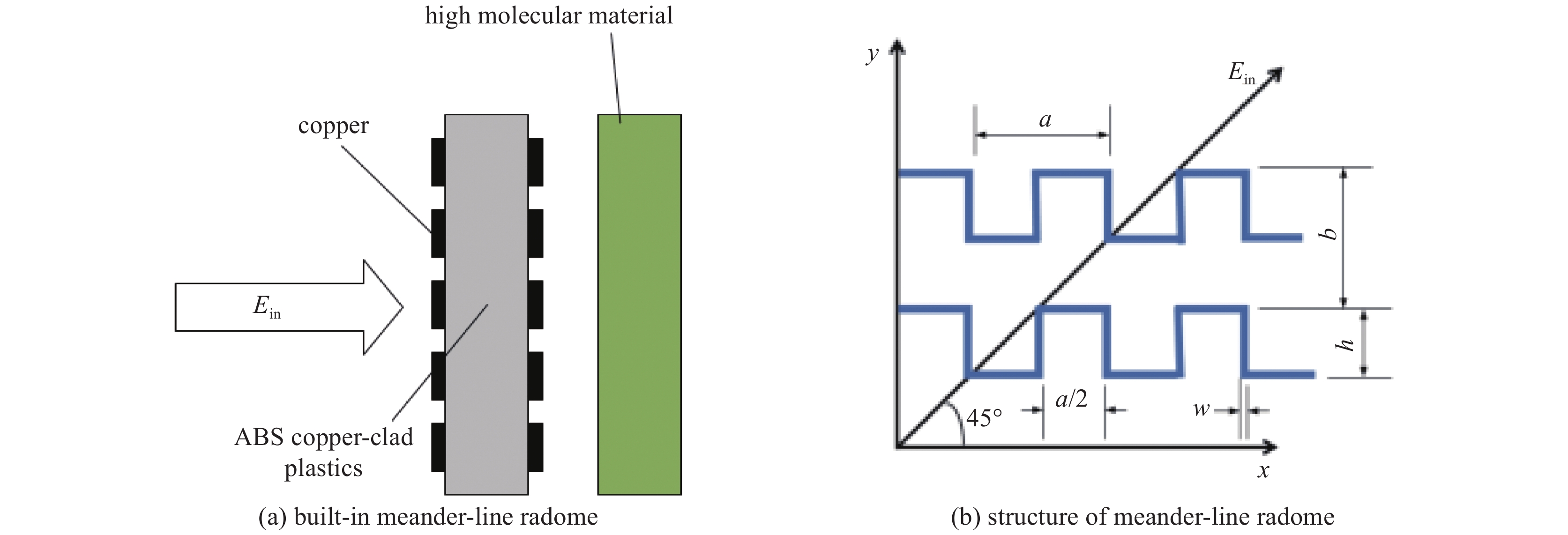
    Fig. 1. Schematic diagram of the structure of the built-in meander-line radome
    Transmission line equivalent circuit for the meander line polarizer observed by Ex and Ey
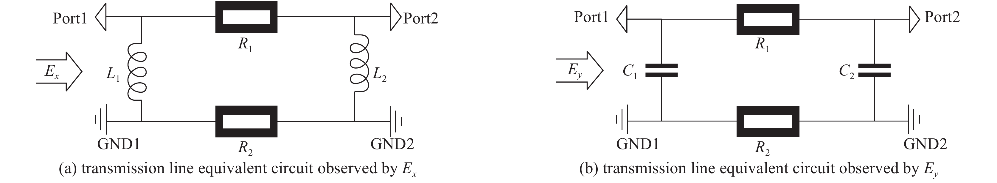
    Fig. 2. Transmission line equivalent circuit for the meander line polarizer observed by Ex and Ey
    The model of element and the electric field distribution
    Fig. 3. The model of element and the electric field distribution
    Electric field analysis of different meander-line radome units
    Fig. 4. Electric field analysis of different meander-line radome units
    Parametric analysis
    Fig. 5. Parametric analysis
    Antenna loaded with built-in curved meander-line polarization conversion radome
    Fig. 6. Antenna loaded with built-in curved meander-line polarization conversion radome
    Antenna performance
    Fig. 7. Antenna performance
    Electric field distribution of antenna array
    Fig. 8. Electric field distribution of antenna array
    Scenario for testing antenna radiation characteristics
    Fig. 9. Scenario for testing antenna radiation characteristics
    Results of the antenna array experiment
    Fig. 10. Results of the antenna array experiment
    The structure and simulation results of the coupler
    Fig. 11. The structure and simulation results of the coupler
    Antenna power capacity test scenario
    Fig. 12. Antenna power capacity test scenario
    Schematic diagram of output waveform of antenna array and radiating horn
    Fig. 13. Schematic diagram of output waveform of antenna array and radiating horn
    a/mmb//mmh/mmw/mmr1/mmr2/mm
    18.524.5174.55.50.5
    Table 1. Parameters of the radome unit
    frequency/GHztest level of standard antenna horn/dBgain of standard antenna horn/dBtest level of antennato be measured/dBgain of antenna to be measured/dB
    4.25−30.519.35−26.3523.5
    4.3−30.5819.42−25.9624.04
    4.35−30.919.50−26.7623.64
    Table 2. Results of experiments
    Guichun Huang, Xiangqiang Li, Gexing Kong, Qingfeng Wang, Jianqiong Zhang. Design and experimental study of high-power built-in curved meander-line polarization conversion radome[J]. High Power Laser and Particle Beams, 2022, 34(2): 023001
    Download Citation