We propose a method for color electroholography using a simple red–green–blue (RGB) gradation representation method without controlling the respective brightness of the reference RGB-colored lights. The proposed method uses RGB multiple bit planes comprising RGB binary-weighted computer-generated holograms with various light transmittances. The object points of a given three-dimensional (3D) object are assigned to RGB multiple bit planes according to their RGB gradation levels. The RGB multiple bit planes are sequentially displayed in a time-division-multiplexed manner. Consequently, the proposed method yields a color gradation representation of a reconstructed 3D object.
Holography[1] is an optical technology that can reliably record and reconstruct three-dimensional (3D) images. 3D images are digitally recorded on computer-generated holograms (CGHs) as an interference fringe obtained from light diffraction calculated by a computer. Electroholography using CGH is expected to enable the ultimate 3D television (3DTV), because it can reconstruct 3D movies using a spatial light modulator (SLM).
Color electroholography is indispensable for developing a 3DTV. Color electroholography using three SLMs for red–green–blue (RGB) lights has previously been reported[2–6]. Likewise, color electroholography using a single SLM has been investigated. Furthermore, the space-division method[7], depth-division method[8,9], and time-division method[10–14] have been proposed.
The study of gradation representation is very useful to yield high quality color representation of reconstructed 3D images using electroholography. A binary CGH can be used in an amplitude-modulation-type SLM, for example, a liquid-crystal display (LCD) panel and a digital micromirror device (DMD). However, the image quality of 3D objects reconstructed from binary CGH is deteriorated due to the error caused by converting holographic data to binary CGH. The gradation representation of the reconstructed 3D images from binary CGH is not easy. Gradation representation approaches using the direct-search method[15,16] and error-diffusion method[17,18] have been reported. The former is an iterative method. The gradation representation approach has also been used for the time-multiplexing technique with multiple bit planes obtained by controlling the intensity of the reference light[19]. However, it is not easy for these approaches[15–19] to freely adjust the gradation of the reconstructed 3D object.
Sign up for Chinese Optics Letters TOC. Get the latest issue of Chinese Optics Letters delivered right to you!Sign up now
In our recent work, a gradation representation method using multiple bit planes composed of binary-weighted CGHs (BW-CGHs) has been proposed[20,21], which provides high quality gradation representation to the respective electroholographies using LCD panels[20] and DMD[21]. In this work, we propose color electroholography using our gradation representation method. We used three transmissive LCD panels of a projector (Epson Corp. EMP-TW1000) as SLMs. A color image is input into the projector and divided into red, green, and blue images. The RGB images are displayed on the LCD panels for RGB reference lights, respectively.
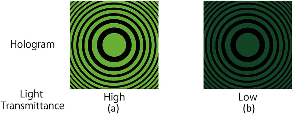
Figure 1 shows the outline of the BW-CGH for green reference light. The BW-CGH shown in Fig. 1(b) is the improved binary CGH for the green reference light. In the conventional binary CGH shown in Fig. 1(a), we used a simple algorithm to obtain an in-inline hologram from a 3D object expressed by a point cloud. The amplitude distribution of the hologram is given by the following equation[22]: where is the amplitude distribution of the point (, , 0) on the hologram, (, , ) is the coordinate of the th point on the 3D object, is the intensity of the object point, is the number of object points of the 3D model, and is the wavelength of the reference light. Equation (1) is obtained using the Fresnel approximation. After the calculation of Eq. (1), the conventional binary CGH is generated from the binarized amplitude distribution of the hologram by a threshold value of zero[23]. As shown in Fig. 1(a), the binary CGH is shown in black and green (bright). Black and green (bright) areas of the binary CGH show that the values of amplitude distribution of the hologram are less than and not less than zero, respectively.
Figure 1.(a) Conventional binary CGH and (b) BW-CGH for green reference light.
The intensity of an object point is set to 1.0 when the binary CGH for a BW-CGH is generated using Eq. (1). Figure 1(b) shows the BW-CGH generated by changing the brightest green color in the binary CGH [Fig. 1(a)] to the green color with one of various gradation levels. The light passing through the green color area of the BW-CGH [Fig. 1(b)] is weakened compared to the light passing through the brightest green color area of the binary CGH [Fig. 1(a)]. Therefore, the light transmittance of the BW-CGH [Fig. 1(b)] is less than that of the binary CGH [Fig. 1(a)].
Figure 2 shows the reconstructed object points from the BW-CGHs displayed on the SLM. Here, object point is reconstructed from the conventional binary CGH, and object points and are reconstructed from the BW-CGHs drawing the green color with different gradation levels. The light intensity of object point is the highest, whereas that of object point is higher than that of object point . Higher gradation levels of the green color on a BW-CGH result in higher light intensity of the reconstructed object point.
Figure 2.Light intensities of the reconstructed object points from BW-CGHs shown in green with various gradation levels.
Figure 3 shows how to assign the respective object points with eight gradation levels to multiple bit planes comprising the BW-CGHs. In Fig. 3, the eight object points with gradation levels ranging from 0 to 7 are assigned to the multiple green bit planes: , , and , respectively. The th green bit plane is described by , and the reconstructed object points from bit plane Bm have 2m gradation levels. Therefore, the reconstructed object points from the bit planes , , and have 20, 21, and 22 gradation levels, respectively. For example, the object point with a gradation level of 5, which is equal to the sum of 20 and 22, is assigned to the bit planes and . The green reference light illuminates the multiple bit planes , , and , which are repeatedly displayed on an LCD panel at a regular time interval Δt, and the 3D gradation image of the object point with gradation level is reconstructed. Here, the intensity of the green reference light is kept constant.
Figure 3.Assignment of the object points of the 3D object to the bit planes comprising BW-CGHs with different gradation levels.
As shown in Fig. 4, the RGB object points with the gradation level of 5 are reconstructed from the RGB bit planes , , and , respectively. Herein, the RGB bit planes , , and are repeatedly displayed on the LCD panels corresponding to the RGB reference lights at a regular time interval . The gray reconstructed object point with the gradation value of 5 is synthesized from the RGB reconstructed object points using the optical setup shown in Fig. 5. Herein, the input color image is synthesized in the th RGB-colored bit plane from the RGB bit planes , , , as shown in Fig. 6. The RGB colors of the respective bit planes are expressed in 8 bit RGB data. Therefore, the synthesized th RGB-colored bit plane is expressed in 24 bit RGB-colored data. The frame rate is inversely proportional to the number of bit planes when the proposed method is adopted to a 3D movie.
Figure 4.Color reconstructed object point from RGB bit planes comprising BW-CGHs with different gradation levels.
We evaluated the proposed method using the optical setup shown in Fig. 5. We used three laser lights with wavelengths of 642, 532, and 473 nm as RGB reconstructing lights for color electroholography, respectively. Each laser light is converted into a parallel light by an objective lens and a collimating lens. The parallel light is made incident on each LCD panel. In Fig. 5, we used three LCD panels mounted on a projector (Epson Inc. EMP-TW1000, L3C07U series). The specifications of the LCD panels are as follows: pixel interval 8.5 μm, resolution , refresh rate , and size . The projector is connected to a PC equipped with an Intel Core i7 3770 (clock speed: 3.4 GHz, quad-core) Linux (CentOS 6.4) as its operating system, the NVIDIA GeForce GTX TITAN as the graphics processing unit (GPU), the CUDA 5.0 software-development kit for the GPU programming, and Open Graphics Library (GL) as the graphics application programming interface (API). In Fig. 5, the mirrors are changed to dichroic mirrors.
In order to evaluate the proposed method, we used the original 3D model “Stanford bunny,” comprising 12,684 object points without hidden surfaces. Figures 7(b)–7(n) show the multicolored reconstructed real images using the original 3D model “Stanford bunny.” Table 1 shows the gradation values of the RGB area of BW-CGHs used in the RGB bit planes: , , , , , , , , . These gradation values were determined using the visual observation of the reconstructed real images from various gradation values because the gradation values of the colored area of BW-CGH can be easily changed.
Figure 7.Multicolored reconstructed real images using the proposed method. (a) The white 3D objects “Stanford bunny” with gradation. (b) The reconstructed real image from the white 3D objects “Stanford bunny.” (b)–(n) The multicolored reconstructed image.
Furthermore, we tried to reconstruct the seven-colored 3D object model. In Fig. 8, the seven-colored 3D object is divided into the red, green, and blue objects, and the object points of the divided respective colored objects assigned to the respective colored multiple bit planes , , , , , , , , and are shown. Figure 9 shows the seven-colored reconstructed real image. Herein, the gradation values of the RGB areas of the BW-CGHs used in RGB bit planes , , , , , , , , and were set to 100, 130, 200, 135, 165, 255, 135, 165, and 255, respectively. The reconstructed real image is composed of seven colors: red, green, blue, cyan, magenta, yellow, and white. The real image shown in Fig. 9 is reconstructed from three RGB multiple bit planes in a time-division-multiplexed manner. Therefore, the real image is displayed at a frame rate of 20 frame/s because the refresh rate of LCD panel is 60 Hz.
Figure 8.Assignment of the object points of the seven-color 3D model to RGB multiple bit planes.
In conclusion, multicolored electroholography was realized using the proposed method without controlling the intensity of the reference light. The proposed method can easily adjust the color of the reconstructed 3D images by changing the gradation value of the RGB areas of the RGB BW-CGHs without controlling the brightness of the reference light. We consider the proposed method to be useful for color adjustment of electroholography.