
Linhui Guo, Lanping Zhang, Yun Fu, Quanwei Jiang, Hao Tan, Weichuan Du, Songxin Gao, Deyong Wu, Chun Tang. Dichroic Mirror Based on Dense Wavelength Combining of High-Brightness Laser Diode[J]. Chinese Journal of Lasers, 2022, 49(9): 0901001
- Chinese Journal of Lasers
- Vol. 49, Issue 9, 0901001 (2022)
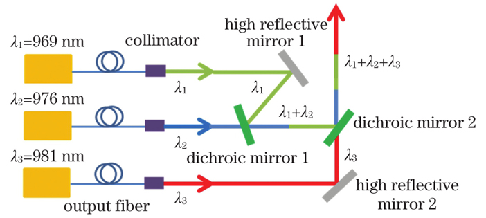
Fig. 1. Structure diagram of dense spectral beam combining of dichroic mirror
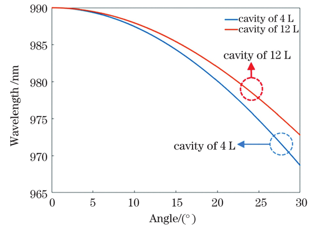
Fig. 2. Incident central wavelength versus incident angle
Fig. 3. Transmission efficiency versus incident angle for laser with different wavelengths
Fig. 4. Principle diagram of laser diode wavelength stabilization
Fig. 5. Measurement curves of power and efficiency of fiber coupling module
Fig. 6. Variation of 976 nm laser wavelength with current or temperature. (a) Variation with current; (b) variation with temperature
Fig. 7. Physical picture of dense spectrum beam combining experiment
Fig. 8. Schematic of common aperture beam combining monitoring optical path
Fig. 9. Axial displacement error of near field and pointing error of far field
Fig. 10. Output power, combining efficiency and spectral curve of combined beam. (a) Output power and combining efficiency; (b) spectral curve
Fig. 11. Three-dimensional display of beam quality of combined beam source
Fig. 12. Temperature monitoring charts of dichroic mirror under different driving current values. (a) Beam combiner 1; (b) beam combiner 2
|
Table 1. Parameters used in simulating the variation of central wavelength with incident angle
|
Table 2. Optimum incident angle and angle bandwidth at different wavelengths
|
Table 3. Spectral parameters of sub-beam source (water temperature of 25 ℃ and current of 11.5 A)
|
Table 4. Divergence angle after collimation of sub-beam laser
| |||||||||||||||||||||||||||||
Table 5. Near field and far field spot of laser
|
Table 6. Measurement of beam quality

Set citation alerts for the article
Please enter your email address
© Copyright 2018-2021 | Chinese Laser Press. All Rights Reserved 沪ICP备15018463号-20