Abstract
A divergent gas-puff Z pinch has been devised for the realization of an efficient soft x-ray point source. In this device, a divergent hollow annular gas puff is ejected outward from the surface of the inner electrode, and the plasma is compressed three-dimensionally to generate a soft x-ray point source. In the SHOTGUN III-U device at Nihon University, the power supply was enhanced, and experiments were conducted over a larger current range. The peak current at the charging voltage of -25 kV was -190 kA. Ar was used as the discharge gas. The self-contraction process of the plasma was investigated in detail using a gated camera. Near the peak current, local contraction occurred in front of the inner electrode. The contraction velocity of the plasma was 5.5 × 10⁴ m/s. As the plasma contracted, the discharge current decreased. The energy input was analyzed by induction acceleration. The net input energy was found to be 750 J, which corresponded to 13.3% of the stored energy of the capacitor, 5630 J. The soft x-ray source was observed using a soft x-ray CCD camera. A point source was observed 7 mm in front of the inner electrode. The size of the source was 35 μm in the axial direction and 14 μm in the radial direction.
I. INTRODUCTION
The plasma focus was invented by Fillipov and Mather.1,2 The notable feature of this device is that the discharge is performed in a gas-filled state, and the plasma contracts as the gas collects and converges to a single point in front of the center electrode. Rayleigh–Taylor instability does not occur during plasma contraction. Neutrons can easily be generated by discharges using D2 gas.3 However, this neutron generation is nonthermal and is described by a beam target model associated with ion beam generation.4 In a plasma focus, since the discharge starts with surface discharge of an insulator, the input energy is limited by deterioration of the insulator.5 In addition, soft x-ray sources using a plasma focus have been investigated.6
Gas-puff Z pinches have been invented by Shiloh, Burkhalter, and their co-workers.7,8 Experiments were carried out using a pinhole nozzle and later an annular nozzle, with an isolated gas column being formed in a space using a supersonic gas jet. High-temperature and high-density plasmas were obtained even in small-scale devices, and soft x-rays were emitted.
To realize an efficient soft x-ray point source, a divergent gas-puff Z pinch has been devised that both exhibits convergence of the plasma focus and has the efficiency of a gas-puff Z pinch. In initial experiments on the device, high-energy x-rays of about 200 keV were observed, and it became clear that electron acceleration had occurred.9 Furthermore, high-energy ions of about 1 MeV were observed. High-energy ions were observed even when the direction of the current was reversed, and it was confirmed that the ion acceleration was independent of the direction of the current.10 Soft x-ray spectroscopic measurements have been performed to examine the differences in spectra depending on the direction of the current.11 The spatial structures of K- and L-shell radiation from Ar ions have been investigated by observations using soft x-ray CCD cameras.12
The X pinch is an excellent x-ray point source with a small source size.13 The problem with the X pinch as a soft x-ray point source is that the spectra of the multiply charged ions in a high-temperature plasma and the hard x-rays due to the electron beam are mixed. By contrast, the divergent gas-puff Z pinch can act as a soft x-ray point source with a limited spectrum.
In the experiment described here, the power supply of the SHOTGUN III device was enhanced, allowing experiments in a larger current range. A gated high-speed camera was used to observe the contraction process of the pinch plasma, and the net input energy to the pinch plasma was determined by analyzing the current waveform.
II. EXPERIMENTAL SETUP
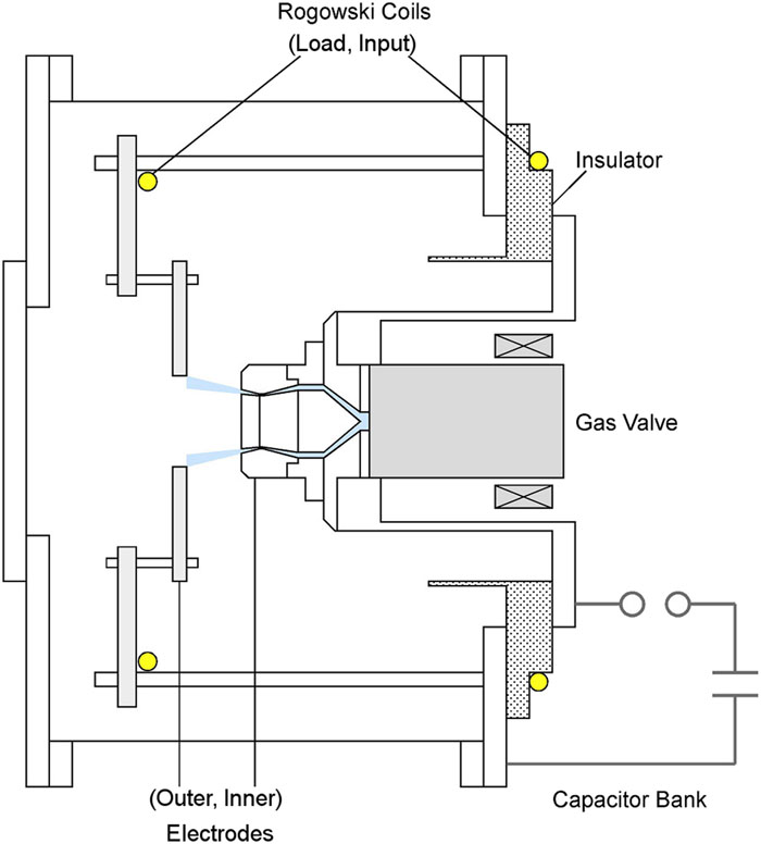
The experiment was conducted with the SHOTGUN III-U Z-pinch device at Nihon University (Fig. 1). The power supply unit of this device is such that it can be charged either positively or negatively. In this experiment, the power supply was enhanced to 40 kV, 18 µF. It was charged to −25 kV to suppress the generation of hard x-rays.

Figure 1.Schematic of the SHOTGUN III-U divergent gas-puff Z-pinch device. The distance between the inner and outer electrodes was 30 mm. The gas was puffed from an annular Laval nozzle on the inner electrode.
The gas puffing was performed by a high-speed gas valve installed behind the inner electrode and a divergent annular Laval nozzle on the electrode. The divergence angle of the nozzle was 10° with respect to the central axis. The inner and outer diameters of the nozzle were 30 mm and 34 mm, respectively, and the opposing outer electrode had a 60 mm hole. Ar was used as the discharge gas, and the plenum pressure of the gas valve was 5 atm. The distance between the inner and outer electrodes was 30 mm.
The discharge currents were measured by Rogowski coils installed on the input side and load side. A scintillation probe (SCI) based on a 3 mm-thick plastic scintillator was used to monitor x-rays. Soft x-rays below 700 eV were blocked by a 5 μm-thick Be window, so that only the K-shell radiation of Ar ions would be captured. The scintillation light was transmitted by an optical fiber to the measurement room, where it was converted into an electric signal by a photomultiplier, so that it became a negative signal. An x-ray diode (XRD) with a Ni photocathode without a filter was used to monitor extreme ultraviolet light. The XRD was not calibrated and could not measure absolute quantities, but it did have a wide sensitivity range from ultraviolet to soft x-rays.14 The XRD mainly captured L- and M-shell radiation from Ar ions. Its signal was also transmitted to the measurement room by photoelectric conversion, but became a positive signal.
To observe the contraction process of the pinch plasma, observations were made using a high-speed camera. This was equipped with a gated image intensifier (Hamamatsu V3063U), and the observations were performed with a gate width of 20 ns.
III. CONTRACTION PROCESS
The gas pressure in front of the nozzle increases with time after the gas puff.13 If the time delay between the discharge and the gas-puff detection is short, a pinch occurs before the current rises to a sufficient level, and so multiple pinches occur. When this happens, the first pinch is the strongest. If the delay time is long, current leakage occurs behind the inner electrode before the pinch, and a strong pinch does not occur. The strength of the pinch was evaluated by the intensity of the SCI signal. Here, the discharge was performed with a delay time of 0.50 ms. Figure 2 shows current waveforms on the input side (“input”) and load side (“load”) and soft x-ray waveforms (SCI and XRD). A sharp peak appears in the SCI signal as the plasma pinches at 1.85 µs after the start of discharge. This indicates the occurrence of the pinch and is set as the origin on the time axis. Since the power supply was charged negatively, the inner electrode was the cathode, and the current also flowed in the negative direction. Before the pinch, the input and load currents were almost equal, and the current value just before the pinch was −190 kA. Both currents were separated after pinching, which indicated that the current path changed. The increase in current is attributed to the decrease in inductance due to the change in the current path. The XRD signal was not large at time 0, but attained a maximum value at around 700 ns. At this time, the SCI signal was small, as was the K-shell radiation.
Figure 2.Discharge currents (input and load) and soft x-ray signals (SCI and XRD). The peak of the SCI signal is set as the origin of time.
Figure 3 shows the state of the plasma observed at various times with the gated camera. The camera could take only one shot for each discharge, but the reproducibility of the discharge was good. The plasma on the front surface of the inner electrode started to contract locally at −294 ns before pinching, and this part contracted rapidly. The radius was 1.3 mm at −50 ns, just before pinching. At 26 ns after pinching, this part was not observable with visible light, and a shock wave was generated in the left uncontracted part. At 700 ns, when the XRD signal became strong, the plasma formed a secondary contraction in the middle of the two electrodes.
Figure 3.Gated images of the pinch plasma at (a) −294 ns, (b) −150 ns, (c) −50 ns, (d) 26 ns, (e) 396 ns, and (f) 700 ns. The locations of the electrodes are shown as white lines. The first pinch occurred in front of the inner electrode, and the second pinch occurred in the middle of the two electrodes.
Figure 4 shows the time dependence of the radius of the plasma on the front surface of the inner electrode. The plasma with the two delay times showed the same shrinkage tendency. The plasma was stationary for a while after the start of discharge, and started contracting at about −0.7 µs. It is assumed that while the plasma was at rest, the electron temperature increased owing to Joule heating, and contraction started after the resistance decreased. The contraction velocity was 5.5 × 10⁴ m/s.
Figure 4.Radius of the pinch plasma vs time. The contraction velocity was 5.5 × 10⁴ m/s.
The gas pressure in front of the nozzle with a delay time of 0.50 ms was 400 Pa.15 Considering the spatial distribution of the gas, the mass of Ar gas was estimated to be 7 × 10⁻⁶ kg/m. The contraction time at a current of 190 kA was estimated to be 0.7 µs. These estimates of mass and contraction time were consistent with the experimental results.
IV. ENERGY TRANSFER
An analysis of the measured current waveform was performed.16 As observed by the gated camera, dynamic contraction occurred in the radial direction. Energy input to the plasma includes Joule heating by resistance and inductive acceleration by radial contraction. Joule heating requires time, and simple circuit analysis cannot determine both resistance and inductance. Here, only the instantaneous energy input due to contraction is considered. Therefore, a simple LCR circuit as shown in Fig. 5 is considered, and only the inductance L is assumed to be time-dependent.
Figure 5.Circuit model for the Z-pinch discharge. Only the inductive part is treated as time-dependent.
The capacitor voltage V is obtained by integrating the current:The charging voltage V0 = −25 kV, and the capacitance C = 18 µF. The circuit equation isThe circuit resistance R = 20 mΩ. By integrating Eq. (2), the inductance L is obtained:The inductance before pinching was 180 nH. It started to increase just before the pinching, and its peak value was 250 nH. The net input energy is the input energy to the load minus the magnetic energy:
Figure 6 shows the voltages V and V − RI, together with the inductance L. The voltage V became −25 kV at the start of the discharge and changed slowly. The inductance L changed from 0.19 µH to 0.25 µH in 30 ns with the pinch. Figure 7 shows the time dependence of the energies. The magnetic energy decreased at the pinch, which contributed to the net input energy. The total input energy at the time of pinching was 3290 J, the magnetic energy was 2540 J, and the net input energy was 750 J. This corresponded to 13.3% of the stored energy of the capacitor, 5630 J. After the pinch, current reconnection occurred, so this circuit model does not hold.
Figure 6.Voltages V and V − RI and inductance L. The inductance increased rapidly at the pinch.
Figure 7.Input energy, inductive energy, and net input energy. The discharge circuit changes after the pinch.
V. HOT SPOT FORMATION
The hot spot was observed using a pinhole camera equipped with a soft x-ray CCD (Fig. 8). The CCD was manufactured by Laser-Laboratorium Gӧttingen e.V. The sensitivity region was <1 nm–1100 nm, and the resolution was 1392 × 1040 pixels (6.45 µm). A Be filter with a thickness of 15 µm was used. Soft x-rays below 1 keV were blocked by the filter. The distance from the center of the device to the pinhole was l1, and the distance from the pinhole to the CCD was l2. The sum of these distances l1 + l2 = 375 mm. The center of the CCD was 5 mm forward in the axial direction from the inner electrode surface. Images were digitized and colored using NIH ImageJ software.
Figure 8.Soft x-ray pinhole camera with CCD. A 15 µm Be filter was used for removing soft x-rays with energies less than 1 keV.
Figure 9 shows the K-shell radiation image of the hot spot taken by the CCD. Here, l1:l2 = 300:75, and a 30 µm pinhole was used. The horizontal direction is the axial direction, and the vertical direction is the radial direction. The position of the inner electrode is indicated by a white dashed line. Only one spot was observed, at a position 7 mm from the inner electrode. To evaluate the spot size, an observation was performed using a 10 µm pinhole with l1:l2 = 195:180. Figure 10 shows an enlarged image of the hot spot taken by the CCD. The spot was 8 pixels (52 µm) in the axial direction and 5 pixels (32 µm) in the radial direction. Considering the image expansion due to the pinhole used for the measurement, the size of the soft x-ray source was 35 µm in the axial direction and 14 µm in the radial direction. The resolution was 7 µm.
Figure 9.K-shell radiating hot spot image taken with a CCD camera. The inner electrode is indicated by the white dashed line.
Figure 10.K-shell radiating hot spot image taken with a magnifying CCD camera.
VI. SUMMARY
Reversed-polarity discharge of a divergent gas-puff Z pinch was conducted using the SHOTGUN III-U device with enhanced power supply. The peak current at the charging voltage −25 kV was −190 kA. Soft x-ray emission with a width of 40 ns was observed with the first plasma pinch. Although the current increased owing to the power supply, the discharge cycle became longer. As a result, the setting of the appropriate delay time from gas puff to discharge changed.
The contraction process of the pinch plasma was observed using a gated camera. Local contraction occurred at the surface of the inner electrode near the peak current. This phenomenon reproduced the previous result.11,12 The contraction velocity of the pinch plasma was 5.5 × 10⁴ m/s.
There was inductive acceleration of the plasma caused by the self-magnetic field. An analysis of the measured current was performed. The total input energy was 3290 J, the magnetic energy was 2540 J, and the net input energy was 750 J. This corresponded to 13.3% of the stored energy of the capacitor, 5630 J. The ratio of the input energy to the stored energy did not change much when the stored energy increased.
The soft x-ray source emitted with the first pinch was observed using a soft x-ray CCD camera. One hot spot was observed, located 7 mm in front of the inner electrode. The size of the spot was 35 µm in the axial direction and 14 µm in the radial direction. As the pinch current increased, the size of the spot became slightly less than the previous result.
References
[1] T. I. Fillipova, N. V. Fillipov, V. P. Vinogradov. Dense high-temperature plasma in a non-cylindrical Z-pinch compression. Nucl. Fusion Suppl., 2, 577-587(1962).
[2] J. W. Mather. Investigation of the high-energy acceleration mode in the coaxial gun. Phys. Fluids Suppl., 7, S28-S34(1964).
[3] E. Baronova, A. Muravich et al. Observation of X-ray emission and neutron yield from a compact plasma focus, 127-133(1999).
[4] A. Link et al. Load designs for MJ dense plasma focus(2017).
[5] W. Kies. Power limits for dynamical pinch discharges. Plasma Phys. Controlled Fusion, 28, 1645-1658(1986).
[6] M. Krishnan. The dense plasma focus: A versatile dense pinch for diverse applications. IEEE Trans. Plasma Sci., 40, 3189-3221(2012).
[7] N. Rostoker, A. Fisher, J. Shiloh. Z pinch of a gas jet. Phys. Rev. Lett., 40, 515-518(1978).
[8] A. Fisher, J. Shiloh, R. D. Cowan, P. G. Burkhalter. X-ray spectra from a gas-puff z-pinch device. J. Appl. Phys., 50, 4532-4540(1979).
[9] K. Takasugi et al. Hard X-ray radiation from a Z-pinch with divergent gas-puff. Plasma Fusion Res., 2, 036(2007).
[10] M. Nishio et al. Ion acceleration independent of the electric current direction in Z-pinch plasma. Plasma Fusion Res., 6, 1201009(2011).
[11] V. Shlyaptseva, K. Takasugi et al. Radiative characteristics of reversed polarity gas-puff Ar and Kr plasmas. IEEE Trans. Plasma Sci., 46, 3842-3848(2018).
[12] M. Nishio, K. Takasugi. Characteristics of Ar K- and L-shell radiations in the divergent gas-puff Z-pinch and the application to contact photography. IEEE Trans. Plasma Sci., 47, 2615-2619(2019).
[13] T. A. Shelkovenko, S. A. Pikus, D. A. Hammer. X-Pinch. Part I. Plasma Phys. Rep., 41, 291-342(2015).
[14] D. J. Nagel, E. B. Saloman, P. Lee, R. H. Day. X-Ray Diodes for Laser Fusion Plasma Diagnostics(1981).
[15] H. Takada, A. Takeuchi, T. Miyamoto, K. Takasugi. Operating regions of a gas- puff Z-pinch and its X-ray radiation. Jpn. J. Appl. Phys., 31, 1874-1878(1992).
[16] K. Takasugi, H. Suzuki, K. Moriyama, T. Miyamoto. Energy transfer to gas- puff Z-pinch and X-ray radiation. Jpn. J. Appl. Phys., 35, 4051-4055(1996).