1State Key Laboratory of High Field Laser Physics, Shanghai Institute of Optics and Fine Mechanics, Chinese Academy of Sciences, Shanghai 201800, China
2University of Chinese Academy of Sciences, Beijing 100049, China
3Department of Physics, Shanghai Normal University, Shanghai 200234, China
Shasha Li, Baifei Shen, Wenpeng Wang, Zhigang Bu, Hao Zhang, Hui Zhang, Shuhua Zhai, "Diffraction of relativistic vortex harmonics with fractional average orbital angular momentum," Chin. Opt. Lett. 17, 050501 (2019)
Copy Citation Text
Vortex harmonics with fractional average orbital angular momentum are generated when a relativistic fractional vortex beam is incident on and reflected from an over-dense plane plasma target. A two-step model is presented to explain the far-field patterns of the harmonics. In the first step, a fundamental spot-shaped hole is produced during the hole-boring stage, and harmonics are generated simultaneously. In the second step, different order harmonics are diffracted by the hole and propagate to the far field. This process can be accurately described by the Fraunhofer diffraction theory. This work facilitates a basic recognition of fractional vortex beams.
Light beams carry both spin angular momentum (SAM) and orbital angular momentum (OAM) in their direction of propagation. The average value of the SAM is associated with the polarization state, zero for linear polarization and and for left and right polarization, respectively. The OAM is related to the spatial structure of wave fronts. Beams with an azimuthal phase term have an OAM that is linked to the azimuthal component of the Poynting vector[1,2], where is the topological charge (TC), and is the azimuthal angle. There is a dark point in the transverse intensity because such a field has an on-axis singularity profile. In particular, it has been verified that the OAM of a vortex beam enables them to rotate trapped particles and have a great application in optical micromanipulation[3–6]. These vortex beams can be generated in many ways, such as the geometric optics mode conversion method[7], computational holography[8], spatial light modulator[9,10], and spiral phase plate (SPP)[11,12].
However, the majority of previous studies have investigated integer vortex beams, and focused optical vortices have also been studied[13,14]. Very few studies have examined the relativistic mechanism of fractional vortex beams[15]. In contrast to the circularly symmetric intensity of integer vortex beams, fractional vortex beams have a gap on the bright ring, which means that fractional vortex beams may provide more controllable parameters. Increasing attention has been given to fractional vortex beams[16–23] because of their unique advantage in optical communications, particle handling, and other applications. In 2004, Berry[16] studied fractional vortex beams for the first time, to the best of our knowledge. It was noted that fractional optical vortices are formed by the linear superposition of infinite integer vortices and that the half-integer TC is a critical condition in the generation of a new vortex. Diffraction, one of the fundamental properties of a beam, has been studied for integer and fractional vortex beams by many groups[24–27]. Colorful diffraction patterns are always related to the TC of the beam and facilitate numerous new means of detection. In addition, the evolution of the diffraction patterns has some guiding significance for the study of relativistic fractional vortex beams. The relativistic vortex beam can be defined in the same way as a Gaussian beam. The normalized dimensionless number is defined as the normalized vector of the laser, where is the elementary charge, is the potential of the light field, is the electron mass, and is the vacuum speed of light. When , the transverse speed of the electron is close to the speed of light. Therefore, the intensity corresponding to is defined as the relativistic threshold of laser intensity.
In this study, the diffraction of fractional vortex harmonics is investigated for a relativistic fractional vortex beam irradiating a plasma target, which is successfully explained by a two-step model. In the first step, the fractional vortex beam is incident on the target and produces a spot-shaped hole during the hole-boring (HB) stage, and harmonics are generated simultaneously. In the second step, harmonics are diffracted by the hole and propagate to the far field, which is calculated using the Fraunhofer diffraction theory. Besides, the diffraction of harmonics driven by the fractional vortex beams is compared with cases of integer vortex beams, which show that the diffraction effects on the generation of harmonics become apparent with an increase in the harmonic order for both fractional and integer vortex beams. This work facilitates not only a basic recognition of fractional vortex beams but also suggests some possible detection procedures for the vortex beams with fractional average OAM in the relativistic region according to the far-field diffraction patterns of harmonics, which is important for potential applications in quantum information and multiple microparticle trapping and manipulation.
Sign up for Chinese Optics Letters TOC. Get the latest issue of Chinese Optics Letters delivered right to you!Sign up now
In the first step, three dimensional (3D) particle-in-cell (PIC) simulation based on EPOCH[28] code is performed to elucidate the mechanism of the fractional vortex beam irradiating an over-dense plasma target. At , the mode of the driving fractional vortex beam is , which means that the phase increases by in a circuit of the origin. The fractional vortex beam can be expanded by integer Laguerre–Gaussian (LG) modes. Here, the LG modes are described as
In this simulation, , and the wavelength of the beam is μ. is the laser period. is the azimuthal index, and is the azimuthal coordinate. The laser pulse has a normalized amplitude of and a pulse duration of 27 fs (full width at half-maximum), where is the elementary charge, is the laser electric field amplitude, is the electron mass, is the fundamental frequency, and is the vacuum speed of light. The focal spot radius of the beam is . A sketch of the simulation is shown in Fig. 1(a). The plasma target occupies the region in the propagation direction of the incident laser beam, and in the transverse direction. To be realistic, a pre-plasma is set at the front of the target before the arrival of the main pulse, and the electron density distribution can be expressed as where is the critical density. The simulation box is , and the number of spatial grids is . Each is filled with two macro electrons and two macro protons. At , the laser pulse enters the simulation box normally from the left boundary. It should be noted that the electric field and the electron density are normalized to and , respectively, in the simulation.
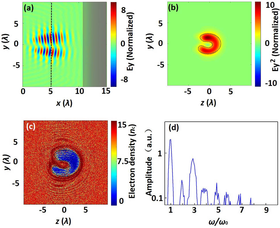
Figure 1.(a) Electric field of the incident pulse in the x–y plane at at . (b) Transverse intensity distribution of the incident beam averaged for the entire pulse at [the black dotted line in (a)] at . (c) Electron density distribution at when the pulse arrives at the target surface. The black lines in (b) and (c) are the outlines of the 1/e maximum intensity of the incident beam and the hole of the target. (d) Frequency spectrum of the laser field after interaction between the input pulse and target. The field signal corresponds to and at .
At , the relativistic fractional vortex beam completely enters the simulation window, and the longitudinal electric field amplitude is shown in Fig. 1(a). The corresponding transverse intensity distribution averaged over the entire pulse is shown in Fig. 1(b). This result indicates that the beam has a gap on the bright ring, which can provide more controllable parameters. When the pulse interacts with the target, electrons are expelled from the high intensity region to the low intensity region of the laser as a result of the pondermotive force of the fractional vortex beam. As seen in Fig. 1(c), the electrons are expelled, and a hole is formed during the HB[29] process. Compared with the transverse intensity distribution in Fig. 1(b), it can be clearly seen that the hole shape on the target is the same as intensity shape of the incident beam.
When the relativistic fractional vortex beam interacts with the target, both a spot-hole and harmonics are generated simultaneously. The harmonics are reflected from the target and propagate to the far field. As shown in the frequency spectrum in Fig. 1(d), harmonics that are generated in the reflected beam are recorded at . Here, the main harmonics are of odd orders, which agrees well with the results of the vortex oscillating mirror (VOM) model[30]. In the VOM model, the electron surface oscillates harmonically against a fixed ion background and radiates harmonics. Its oscillation phase consists of two parts. The first part arises from the ponderomotive force, which leads to the mirror oscillation in the longitudinal direction. The second part is derived from the transversally nonuniform ponderomotive force due to the vortex beam. However, some weak even order harmonics also appear, which may be caused by the intrinsic helicoid wavefront of the incident vortex beam, as well as the deformation of the target. Although the fractional vortex beam is incident normally on the target, the wavefront forms a small angle with the incident surface, resulting in the generation of both odd and even harmonics. In this case, we mainly consider the strong odd order harmonics in this Letter. Here, it should be noted that there appears to be a red shift, especially for high order harmonics due to the HB process.
The electric fields of the harmonics for the fractional vortex beam are asymmetric, and the corresponding average OAM is expected to be fractional, which is different from the case of the integer vortex beam. The transverse electric fields and intensity distributions of harmonics in the near-field are shown in Fig. 2. Figures 2(a1)–2(d1) show the transverse electric field distributions, and Figs. 2(a2)–2(d2) show the intensity distributions of the first, third, fifth, and seventh harmonics of the reflected beam at at . There is still one gap on the bright ring in the transverse intensity distributions of the harmonics, which are “C”-like shapes that are similar to the density shape of the incident fractional vortex beam [Fig. 1(b)].
Figure 2.Reflected transverse electric field distributions of the (a1) first, (b1) third, (c1) fifth, and (d1) seventh harmonics in the z–y plane at and . Corresponding transverse intensity distributions of harmonics averaged on entire pulse are shown in (a2)–(d2).
The 3D PIC simulation illustrates the first step well, where a fractional vortex beam is incident on a target and produces a spot-shaped hole during the HB stage, and harmonics are generated simultaneously. However, what can be measured by a charge-coupled device (CCD) in actual experiments are transverse patterns in the far field. Because the accuracy and simulation distance in the PIC simulation are limited, only harmonics in the near-field can be obtained. Therefore, harmonics propagating to the far field should be considered, which can be realized by diffraction theory in the second step.
Before analyzing the diffraction in the second step, it is necessary to determine the specific expressions of the fundamental and harmonics of the fractional vortex beam. The expressions can be obtained by the following steps. Firstly, the mode of the th harmonic is obtained based on the conservation of the average OAM. Secondly, the fractional vortex harmonics are expanded using integer modes, and their OAM spectrum is shown. The objective of this step is to obtain a reasonable superposition range of integer modes. Finally, the specific expressions of each fractional vortex harmonic are obtained by expanding into the superposition of a finite reasonable number acquired in the last step.
Firstly, for the vortex beam with fractional average OAM, its mode is related to its average OAM, which is expressed as[20]
It has been verified that the average OAM is conservative during the harmonic generation of fractional vortex beams[15,31,32], where . Therefore, based on the conservation law of the average OAM, the mode of the th harmonic can be derived as
Figure 3 shows the relation between the mode of the th harmonic and the harmonic order for the fundamental frequency beam with . This is different from the scaling relation (the gray dotted line) for an integer vortex beam between and the harmonic order . It can be determined that the modes of the first, third, fifth, and seventh harmonics are , , , and , respectively.
Figure 3.Relation between the mode of the th harmonic and its harmonic order for the fundamental frequency beam with . The gray dotted line is the scaling relation between and the harmonic order .
Secondly, the fractional vortex beam can be expanded by the superposition of integer vortex beams, and the superposition is determined by the Fourier series
Thus, the probabilities of each integer mode are , where is the th integer mode with a TC . Therefore, the OAM spectrum of different harmonics can be obtained as shown in Fig. 4. It is clearly shown that a vortex beam with fractional average OAM is superposed, mainly by its nearest two integer modes (0 and 1 for , 2 and 3 for , 4 and 5 for , 5 and 6 for ). Therefore, it is sufficient to superpose the integer modes from to 100 in our following calculation.
Figure 4.Superposition of (a) first, (b) third, (c) fifth, and (d) seventh harmonics for different integer modes.
Finally, it has been demonstrated that the paraxial fractional vortex field propagating in the direction with a Gaussian intensity distribution can be described as[16] (normalized to wavenumber ) where is the Gaussian spot width. , and is the Bessel function of the first kind. Based on the OAM spectrum in the last step, it is reasonable to take the from to 100. Therefore, the fractional vortex beam can be expressed by
Thus, the specific expressions of the fundamental and harmonics of the fractional vortex beam have been acquired.
The far-field diffraction patterns of the harmonics can be obtained by performing a Fourier transform of the complex amplitude distribution on the hole plane in space, given by where , are spatial frequency, , . In our calculation, the electric field before the hole is described by Eq. (8), where . The shape of the hole is defined by the contour of the 1/e maximum intensity of the fundamental frequency. The transmittances inside and outside the hole are 100% and zero, respectively. The receiving screen is placed in the far field ( in our calculation, which is considered infinite) behind the hole. It should be noted that what we are interested in is the morphology of these intensity profiles, which are normalized to the maximum intensity of the incident beam.
According to the aforementioned theory, the diffraction patterns of the harmonics for the fractional vortex beam in the far field can be obtained. As shown in Figs. 5(a1)–5(d1), the mode of the incident fractional vortex beam is , and the hole has the same shape as the incident beam, which is shown in the bottom left of Fig. 5(a1). The first to seventh harmonics are diffracted by the hole, and the corresponding diffraction patterns in the far field are shown in Figs. 5(a1)–5(d1). This result indicates that the transverse diffraction patterns are still generally “C”-shaped, but the spots split into several irregular lobes in the inner part and broken diffraction fringes in the outer part. Besides, the distortion becomes heavier with an increase of the harmonic order.
Figure 5.Fraunhofer diffraction patterns of first, third, fifth, and seventh order harmonics of fractional (first row) and integer (second row) vortex beams under different conditions. The illustrations in the bottom left of the first column are corresponding holes. (a1)–(d1) Fundamental fractional vortex beam with diffracted by the hole shape of . (a2)–(d2) Fundamental integer vortex beam diffracted by the hole shape of .
In the case of the integer vortex beam, considering the LG beam for example, an annular hole[33] can be produced in the first step, as shown in the bottom left of Fig. 5(a2). For the case of , the diffraction patterns of all the harmonics are regular concentric diffraction rings. With an increase of the harmonic orders, more diffraction rings appear, and the radius of the hollow structure becomes larger because the TC is proportional to the harmonic order.
Comparing the diffraction patterns of harmonics for fractional and integer vortex beams, it can be found that different harmonics have their own unique characteristics. Consequently, the diffraction patterns may provide some potential detection methods for the vortex beam with fractional average OAM during relativistic interaction according to the far-field diffraction patterns of the harmonics.
From the calculations and previous discussions, it can be concluded that the Fraunhofer diffraction pattern is mainly determined by the hole shape, while the hole shape is determined by the shape of the incident laser beam. Therefore, the far-field diffraction patterns of the harmonics are mainly related to the incident laser, as demonstrated by our two-step model.
It has been shown that harmonics can be generated and propagate to the far field when a relativistic fractional vortex beam irradiates a solid target. The details of this process were successfully calculated using a two-step model. In the first step, a fundamental spot-shaped hole is produced by an incident fractional vortex beam, and harmonics are generated simultaneously. In the second step, harmonics are diffracted by this hole and propagate to the far field. This work not only is of fundamental importance for the understanding of the relativistic fractional vortex beam interaction with plasmas, but also suggests some potential detection procedures for the vortex beam with fractional average OAM during relativistic interaction based on the far-field diffraction patterns of harmonics, which is important for potential applications in quantum information and multiple microparticle trapping and manipulation.