
Shuai-Ling Sun, Yong-Gang Leng, Yu-Yang Zhang, Xu-Kun Su, Sheng-Bo Fan. Analysis of magnetic force and potential energy function of multi-stable cantilever beam with two magnets [J]. Acta Physica Sinica, 2020, 69(14): 140502-1
- Acta Physica Sinica
- Vol. 69, Issue 14, 140502-1 (2020)
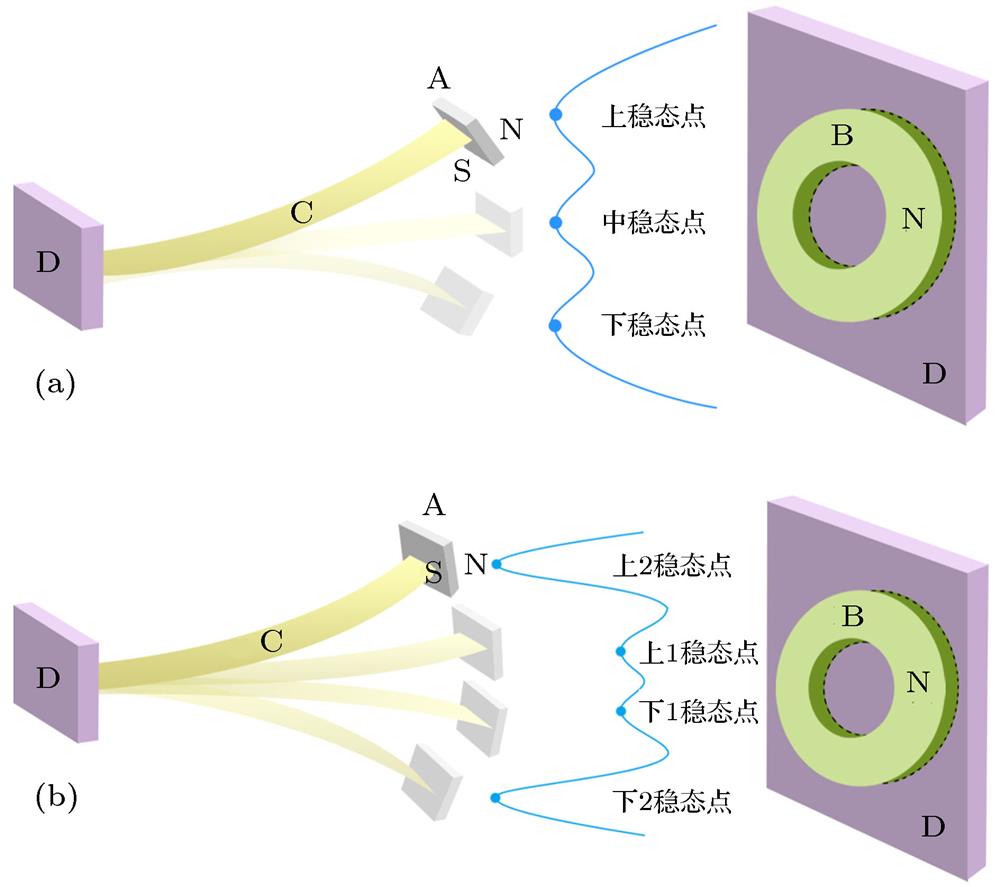
Fig. 1. Multi-stable cantilever beam with two magnets: (a) The state concluding three stable points; (b) the state concluding four stable points.
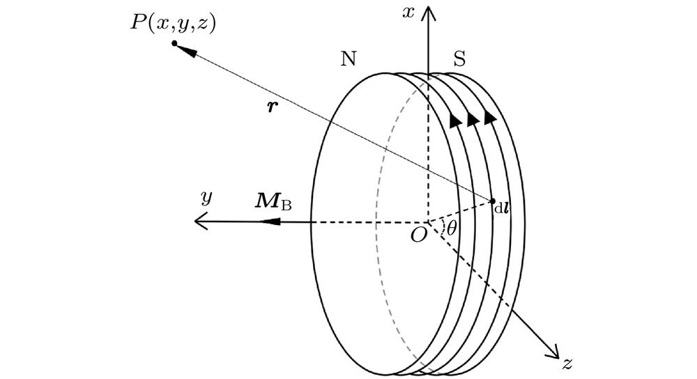
Fig. 2. Schematic diagram of there-dimension coordinate system and magnetizing currents on the surface of the circular magnet.
Fig. 3. The curves of Bi and Bj varying with x : (a) The curves of Bi varying with x , y = 6.0 mm; (b) the curves of Bj varying with x , y = 6.0 mm; (c) the curves of Bi varying with x , y = 10.0 mm; (d) the curves of Bj varying with x , y = 10.0 mm.
Fig. 4. Magnetic induction intensity measurement system: (a) The measurement of Bi ; (b) the measurement of Bj .
Fig. 5. The position of the rectangular magnet in coordinate system when the cantilever beam is bent.
Fig. 6. Two kinds of calculation of the position of the magnet at the free end of the beam.
Fig. 7. Displacement measuring device.
Fig. 8. Schematic diagram of the size of the rectangular magnet and the magnetizing currents on the surface of the rectangular magnet.
Fig. 9. The curves of Fi and Fj varying with x C: (a) The curves of Fi varying with x C, d = 5.8 mm; (b) the curves of Fj varying with x C, d = 5.8 mm; (c) the curves of Fi varying with x C, d = 8.0 mm; (d) the curves of Fj varying with x C, d = 8.0 mm.
Fig. 10. Magnetic force measurement system: (a) The measurement of Fi ; (b) the measurement of Fj .
Fig. 11. The system potential function varying with d when the size of the rectangular magnet is 10 mm × 10 mm × 3 mm and the ring magnet is 40 mm (φ 1) × 20 mm (φ 2) × 3 mm: (a) Three dimensional diagram of system potential function; (b) two dimensional diagram of system potential function when d = 3 mm, d = 6 mm and d = 20 mm.
Fig. 12. The system potential function varying with d : (a) The size of the rectangular magnet is 20 mm × 20 mm × 3 mm; (b) the size of the rectangular magnet is 30 mm × 30 mm × 3 mm.
Fig. 13. The system potential function varying with l A when d = 6 mm and the size of the ring magnet is 40 mm(φ 1) × 20 mm(φ 2) × 3 mm: (a) Three dimensional diagram of system potential function; (b) two dimensional diagram of system potential function when l A = 3 mm, l A = 10 mm, l A = 20 mm, l A = 30 mm and l A = 45 mm.
Fig. 14. (a) The curves of W 2 and W 3 varying with x C when l A = 20 mm and l A = 30 mm; (b) the curves of Fi varying with x C when l A = 20 mm and l A = 30 mm.
Fig. 15. The structure concluding three stable points: (a) The middle state point; (b) the upper stable point.
Fig. 16. The structure concluding four stable points: (a) The upper stable point 1; (b) the upper state point 2.
Fig. 17. The vibration response of the tri-stable cantilever beam: (a) The time domain chart; (b) the phase chart.
Fig. 18. The vibration response of the quad-stable cantilever beam: (a) The time domain chart; (b) the phase chart.
|
Table 1.
Materials and parameters of cantilever beam, rectangular magnet, and ring magnet.
悬臂梁、矩形磁铁、环形磁铁的材料和参数
|
Table 2.
Experimental equipments and models.
实验器材及其型号

Set citation alerts for the article
Please enter your email address
© Copyright 2018-2021 | Chinese Laser Press. All Rights Reserved 沪ICP备15018463号-20