
Jiapeng Yin, Xiaohui Yuan, Zusheng Zhou, Guoxi Pei, Shengguang Liu. Novel electron source based on interaction between high power laser and metal wire[J]. High Power Laser and Particle Beams, 2021, 33(9): 094003
- High Power Laser and Particle Beams
- Vol. 33, Issue 9, 094003 (2021)
Abstract
Electron beam has been playing an important role in the field of basic scientific research,industrial production,and medical treatment. Electron beams are all generated and accelerated in the accelerator. As we all know,electron source is an important component of the electron accelerator,which has two functions: One is to generate enough electrons,and the other is to accelerate these electrons to a certain speed immediately,better to a relativistic speed,which can effectively suppress the negative influence of space charge effect on the quality of the electron beam. For an accelerator,the quality of the electron beam is largely determined by the electron source[
1 Experimental setup
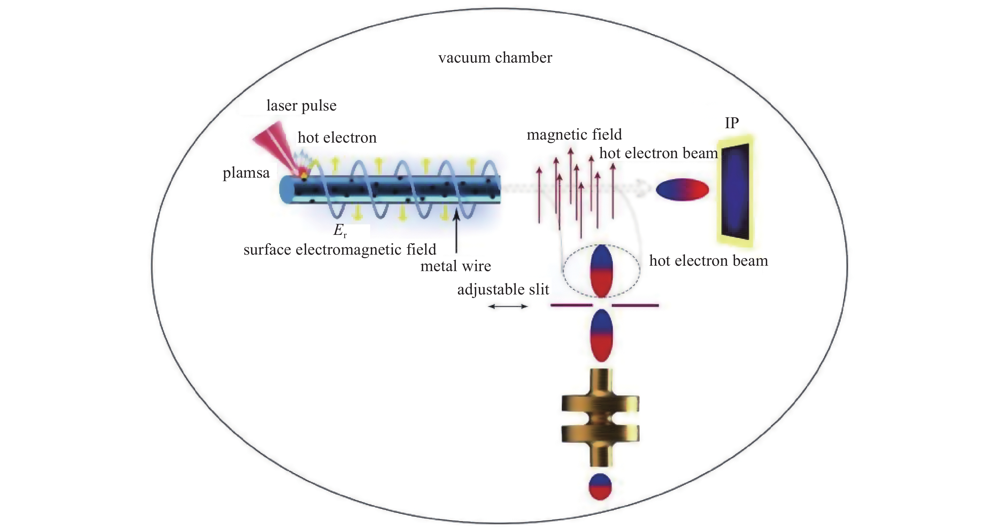
The layout of the novel electron source is shown in Fig.1. Experiment was carried on the 200 TW laser facility in Shanghai Jiaotong University. A Ti:sapphire laser system provides the laser pulses,with 1 J per pulse,800 nm, and 150 fs pulse duration. The maximum repetition rate is 10 Hz,and it can also operate in single-shot mode. In experiment,the laser pulse is finely focused on the wire at a spot size of 6 μm,resulting in a peak density of about 1019 W/cm2. The experiment was conducted in a vacuum chamber, whose vacuum is about 10−2 Pa. Downstream of the wire target,we use imaging plates (IPs,Fujifilm SR2025) to measure the electron beam distribution,and a Faraday-cup can be used to measure the bunch charge. A uniform dipole magnet is put just behind of the wire end to rotate all electrons 90°,and the size of magnet is 150 mm×100 mm×10 mm. The magnetic field intensity in the central area of the two magnets is 0.139 T. An adjustable slit can be used to choose the bunch charge and energy spread by optimizing the position and width,as electrons in different velocity rotate at different radius. In the experiment,the slit width is 0.1 mm,and the horizontal distance between the slit and the end of the wire target is 8 mm. The chosen electron bunch downstream the slit is much long for RF acceleration,thus it enters an RF compressor to be compressed short enough for the main accelerator. We have measured three metal wires W,Cu and Ag with different diameter.
![]()
Figure 1.Experimental layout
2 Results and discussion
2.1 Beam profile
Fig.2 is the electron image on IP board. In this case,W wire has the diameter 0.03 mm,the distance from the laser focusing point to the end of the wire L is 150 mm. The beam is in ring shape with the maximum diameter about 33 mm,which indicates the electrons propagates forward along the wire surface. The white area indicates the majority of the electrons are within this region that bring the IP board into saturation.
![]()
Figure 2.Electron beam image on IP board. W wire target with
2.2 Electron emission from three metal wires
According to Schottky theory,metal material has a work function. When the electron energy in the material is higher than its work function, electrons escape off the material surface into the vacuum. Different metal has different work function. To find the good electron emission target,we tested three metal wires (W,Ag,Cu) wires with the same diameter and length (d=0.3 mm,L=150 mm). Two samilar IP board layers stack together to detect electron beam profile. Of course,all electrons arrive on the first IP board and imaging. Only those electrons with energy higher than 200 keV can pass through the first IP board layer and reach the second layer. Fig.3 shows the beam profiles on the first IP layer and second IP layer for the three different wire targets. As we know,the beam signal recorded in IP board decays with time due to IP character[
![]()
Figure 3.Electron beam profiles on two-layer IP board for three wires
2.3 Guiding effect on electrons from metal wire
Hot electrons propagate forward along the wire. As discussed above,the electric field and magnetic field around the wire limit and guide the electrons along the wire. We stack three layers of IP board together and put them downstream the W wire end to detect the beam space distribution and energy distribution in the beam bunch. Fig.4 shows beam profile on the three-layer IP board for L=10,20,30 cm respectively. If the distance from the laser focusing spot to the wire end L is longer,the beam can be guided better,thus the beam profile is smaller. Long wire has a better guiding effect on electron beam than short one. Another finding is that the beam size on the first layer is much bigger than that on the second layer. Similarly,the beam size on the second layer is bigger than that on the third layer. This means that the electrons with high power is inside the beam,and the lower energy electrons is outside the beam. There are a few electrons with energy higher than 400 keV from the W wire.
![]()
Figure 4.Electron spatial distribution on three-layer IP board for tungsten wire of different length
2.4 Energy spectrum
From the beam profile on IP board,we can deduce the energy distribution of the beam from the metal wire. To get energy spectrum exactly,we insert a dipole magnet just behind the wire to make all electrons rotate 180°,and hit on the IP board. From the beam position,distribution,and magnetic field,we can calculate the energy spectrum of the beam. Fig.5 shows the beamlet and energy spectrum. In this case,the laser intensity is about 1019 W/cm2,the Cu wire is 150 mm in length and 300 μm in diameter. The electron energy is mostly between 40−240 keV,and an energy peak is at 100 keV. For the same wire,we use a Falady-cup to collect and measure the total charge. 3 nC electron charge can be generated totally in a single shot.
![]()
Figure 5.Beamlet and energy spectrum
3 Start-to-end simulation for bunch compression
As Fig.5 shows,the charge of the electrons with 95−100 keV energy is estimated at nC level,and the bunch length is estimated about 55 ps after drifting a 150 mm distance from the laser focusing spot. To the main accelerator generally,bunch charge is high enough,but bunch length is too long. For example,we suppose the main accelerator is S-band,2856 MHz,one RF duration is 350 ps. We put forward a compression scheme: Firstly,selecting the electrons by a magnetic field and an adjustable slit,and then injecting them into an RF cavity. Fig.6 shows the electric field in a 2-cell RF cavity. When an electron bunch with a certain length enters the microwave electric field,electrons at different position of the bunch experience different electric field. We can choose a proper time to inject the electron beam into the RF cavity,so that the head electrons of the bunch feel low electric field and gain a small mount of energy,but the tail electrons of the bunch feel high electric field and gain a lot of energy. After the bunch passed through the cavity,the tail electrons move faster than the head electrons. After drifting a distance,the tail electrons catch up with the head electrons gradually. As a result,the bunch length is compressed. The required RF peak power is estimated only 10−30 kW.
![]()
Figure 6.
We simulated the compression effect of the RF cavity on the electron bunch with ASTRA (A Space Charge Tracking Algorithm) code. ASTRA is a beam dynamics simulation software. User defines the initial distribution of particles and external electromagnetic field;it can track the particles under the influence of external fields and space charge effect. It is assumed that all electrons are generated from the laser focal point of 6 μm diameter at the same time,then they drift along 150 mm wire. Arriving at the end of wire,the electron bunch length of 95−105 keV increases to about 9 mm (RMS) in space,about 55 ps in time,as shown in Fig.7. The first step is to find the optimized injection phase for electron beam into RF cavity. Fig.8 shows the relation between bunch length and the injection phase.
![]()
Figure 7.Initial distribution of electron bunch
![]()
Figure 8.Bunch length
In simulation,the space charge effect is included. Fig.9 (a) shows that the average energy of the electron bunch increases to about 240 keV. The bunch length can be compressed successfully to around 50% of the original length,from 55 to 27 ps in time,which can be captured and accelerated by the main accelerator.
![]()
Figure 9.Average beam energy in the RF cavity and bunch length (RMS) in the cavity
4 Conclusion
We have generated electron beam by the interaction between relativistic laser and metal wire target experimentally. The beam energy covers 40−240 keV,and the total charge is more than 3 nC. We propose to choose the electrons with energy between 95−100 keV into the buncher cavity,and to compress electron bunch short enough for the main accelerator. We have done start-to-end simulation to optimize the performance of electron beam and successfully compressed bunch length to 27 ps,meanwhile beam energy up to 240 keV. This scheme is a potential electron source for further acceleration in the following main accelerator. Furthermore,this wire source is easy to guide the electron bunch to the experimental position only by pulling the wire,which is beneficial for a lot of applications,such as low energy electron diffraction.
References
[1] Chen Sifu, Huang Ziping, Shi Jinshui. Basic types and technological implementation of charged particle accelerators[J]. High Power Laser and Particle Beams, 32, 045101(2020).
[2] Tokita S, Otani K, Nishoji T, et al. Collimated fast electron emission from long wires irradiated by intense femtosecond laser pulses[J]. Physical Review Letters, 106, 255001(2011).
[3] Nakajima H, Tokita S, Inoue S, et al. Divergence-free transport of laser-produced fast electrons along a meter-long wire target[J]. Physical Review Letters, 110, 155001(2013).
[4] Kania B, Sikora J. System identification of a hot cathode electron source: time domain approach[J]. AIP Advances, 8, 105107(2018).
[5] Qi Fengfeng, Ma Zhuoran, Zhao Lingrong, et al. Breaking 50 femtosecond resolution barrier in MeV ultrafast electron diffraction with a double bend achromat compressor[J]. Physical Review Letters, 124, 134803(2020).
[6] Wu Dai, Bai Wei, Li Ming, et al. Prototype experiment preparation of a 54.167MHz laser wire system f FELTHz facility at CAEP[C]Proceedings of 4th International Particle Accelerat Conference. 2013.
[7] Tabak M, Hammer J, Glinsky M E, et al. Ignition and high gain with ultrapowerful lasers[J]. Physics of Plasmas, 1, 1626-1634(1994).
[8] Hegelich B M, Jung D, Albright B J, et al. Experimental demonstration of particle energy, conversion efficiency and spectral shape required for ion-based fast ignition[J]. Nuclear Fusion, 51, 083011(2011).
[9] Fujioka S, Arikawa1 Y, Kojima S, et al. Fast ignition realization experiment with high-contrast kilo-joule peta-watt LFEX laser and strong external magnetic field[J]. Physics of Plasmas, 23, 056308(2016).
[10] Tian Ye, Liu Jiansheng, Bai Yafeng, et al. Femtosecond-laser-driven wire-guided helical undulator for intense terahertz radiation[J]. Nature Photonics, 11, 242-246(2017).
[11] Yu Tongpu, Ma Yanyun, Chang Wenwei, et al. Numerical simulation on effect of laser parameters on terahertz radiation[J]. High Power Laser and Particle Beams, 20, 943-947(2008).
[12] Zhuo H B, Zhang S J, Li X H, et al. Terahertz generation from laser-driven ultrafast current propagation along a wire target[J]. Physical Review E, 95, 013201(2017).
[13] Chen Min, Shenga Z M, Zheng Jun, et al. Surface electron acceleration in relativistic laser-solid interactions[J]. Optics Express, 14, 3093-3098(2006).
[14] Zhidkov A, Koga J, Hosokai T, et al. Effects of plasma density on relativistic self-injection for electron laser wake-field acceleration[J]. Physics of Plasmas, 11, 5379-5386(2004).
[15] Karmakar M, Chakrabarti N, Sengupta S. Plasma wakefield excitation in a cold magnetized plasma for particle acceleration[J]. Physics of Plasmas, 24, 052111(2017).
[16] Tanaka K A, Yabuuchi T, Sato T, et al. Calibration of imaging plate for high energy electron spectrometer[J]. Review of Scientific Instruments, 76, 013507(2005).


Set citation alerts for the article
Please enter your email address

© Copyright 2018-2021 | Chinese Laser Press. All Rights Reserved 沪ICP备15018463号-20