In this paper, we demonstrate a scheme for compensating distorted optical vortex beams carrying orbital angular momentum. By inputting the intensity profile into the Gerchberg–Saxton algorithm [Optik35, 237 (1972)OTIKAJ0030-4026], the pre-compensation phase mask can be acquired. No additional probe beams are introduced, and all the computing is aiming at the transmitted vortex beams. The distorted vortex beams are investigated experimentally before and after pre-compensation, showing favorable compensation performance. This scheme will find applications in the areas of rotation detection, optical communications, and so on.
Optical vortices, which have helical wavefronts and thus a “doughnut” intensity distribution in the transverse plane, were demonstrated 25 years ago by Allen [1,2]. The complex amplitude of an optical vortex comprises a term of , where is the topological charge and is the azimuthal angle [2]. Each photon in the optical vortices carries orbital angular momentum (OAM) of (where is divided Planck constant) [1,2]. These unique characteristics make optical vortices applicable to areas such as optical tweezing [3], rotation detection [4,5], vector beam generation [6,7], and so on. In particular, optical vortices with different topological charges are orthogonal with each other, which makes it possible to introduce a new mode-division multiplexing in optical data transmission systems [8,9].
A key challenge to utilizing optical vortices in practical applications is that an inhomogeneous medium such as turbulent atmosphere can induce fluctuations in the wavefront or phase. In other words, atmospheric turbulence contributes to the distortion of the helical wavefront of optical vortices, which decreases the received intensity, increases the crosstalk, broadens the OAM spectrum, and so on, finally resulting in degradation of the system’s performance [10,11]. Therefore, it is necessary and important to compensate for the distorted optical vortices.
The standard correction method of a plane wave is invalid for optical vortices due to the helical wavefront. To solve this problem, a Gaussian probe beam is introduced to detect the turbulence, and then the compensating phase masks can be obtained to correct distorted optical vortices [12–14]. For instance, in Refs. [12,13], an additional Gaussian probe was polarized orthogonally, combined with OAM beams, and propagated through the turbulence simultaneously. By detecting the distorted wavefront of the probe Gaussian beam through a Shack–Hartmann wavefront sensor, the correcting phase mask can be obtained; then the correction mask can be used to compensate the distorted single-mode [12] or multiplexed [13] optical vortices. In Ref. [14], a wavefront-free method based on the Gerchberg–Saxton (GS) algorithm is proposed. However, a probe Gaussian beam is necessary. The use of additional probe beams makes the whole system complex and increases the cost. Therefore, it is important to find a scheme which could accomplish corrections of distorted vortex beams without probe beams.
Sign up for Photonics Research TOC. Get the latest issue of Photonics Research delivered right to you!Sign up now
In this paper, we demonstrate a scheme to correct distorted optical vortices without additional probe beams. Unlike the proposal of Xie et al.[15], which used the intensity pattern of distorted OAM beams together with a Zernike polynomial-based stochastic parallel gradient descent algorithm, we show a new non-Zernike GS-based algorithm that can be used to compute the pre-compensation phase mask through the intensity distribution of the distorted vortex beams, where neither the wavefront sensor nor the additional probe Gaussian beam is required.
2. COMPUTING THE COMPENSATION PHASE MASK
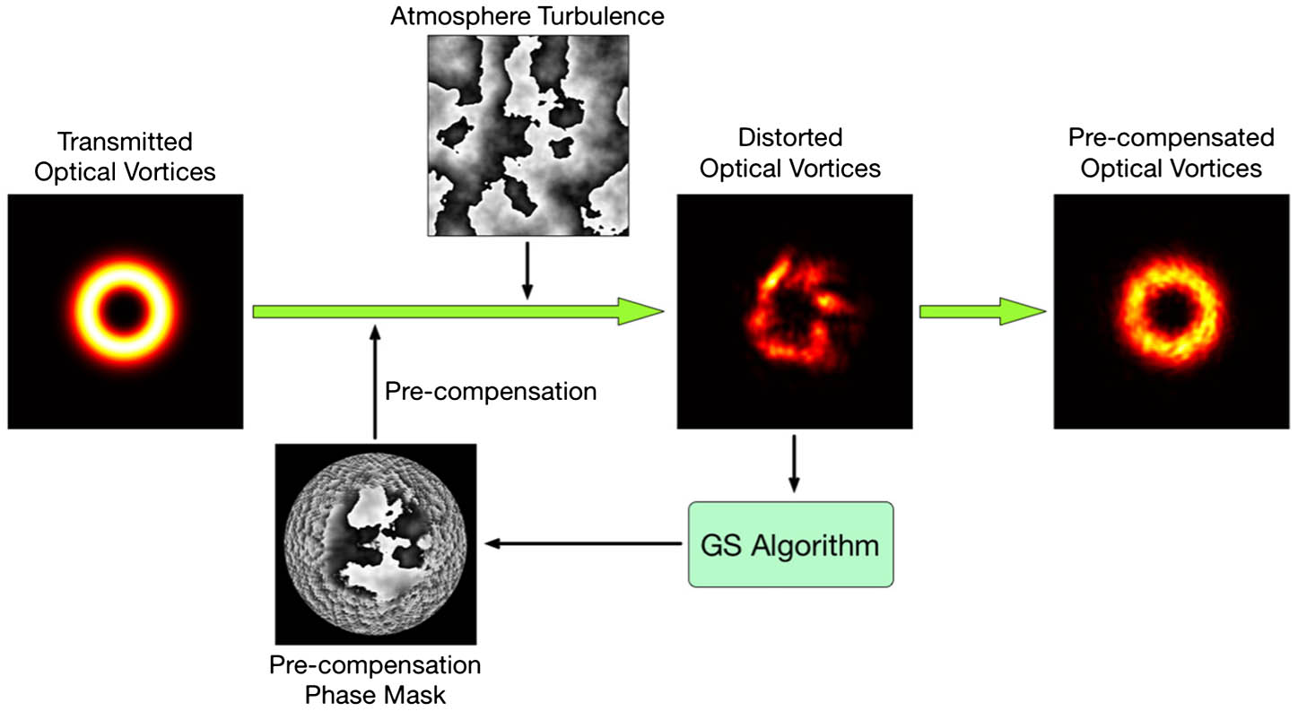
Figure 1 shows the concept of the non-probe GS-based pre-compensation of distorted optical vortices. When a vortex beam propagates through turbulent atmosphere, the distorted wavefront emerges, resulting in irregular intensity profiles. We propose to use a CCD camera to observe the patterns of the distorted optical vortices and apply a GS-based phase-retrieval algorithm; then the pre-compensation phase mask can be obtained as the output of the algorithm. The distorted optical vortices can be corrected well if the compensation is introduced before the turbulence.
Figure 1.Concept of the GS-based non-probe pre-compensation of distorted optical vortices.
The calculation of the pre-compensation mask is based on the GS algorithm, which can be used to determine the phase differences between two wave functions if the intensities in the imaging and Fourier planes are known [16]. Here we show that the pre-compensation mask can be obtained directly when inputting the transmitted optical vortices with helical wavefronts into the GS-based phase-retrieval algorithm, as displayed in Fig. 2(a).
Figure 2.Computing the pre-compensation phase mask based on GS algorithm. (a) Flow chart. (b) can be obtained through subtracting the iteration output from the initial helical phase of the transmitted optical vortices .
Let us begin the algorithm with the complex amplitudes of the transmitted optical vortices, including the “doughnut” amplitude and the helical phase. The optical field in the imaging plane is obtained after the fast Fourier transformation (FFT). Next, we replace the amplitude with that of the distorted optical vortices and use inverse fast Fourier transformation (IFFT) to compute the optical field in the diffraction plane. Then the amplitude is replaced by the initial vortices and FFT is applied continuously. Finally, after undergoing many iterations, the phase distribution in the diffraction plane consists of the initial helical phase and the pre-compensation mask is delivered, which is written as . Then the pre-compensation phase mask is acquired by subtracting from the helical phase as shown in Fig. 2(b), which takes vortices with topological charge as an example. Note that the helical phase here must be that of the transmitted optical vortices.
It must be made clear that all the computing is aimed at the transmitted optical vortices. No additional probe beams are introduced, indicating that correcting distorted vortices directly is possible.
3. EXPERIMENT AND RESULTS
We implement the non-probe, GS-based pre-compensation of distorted optical vortices by employing the setup shown in Fig. 3. Gaussian beams emitted from a laser diode (LD) with a wavelength of 1550 nm are coupled into a single-mode fiber (SMF) and then collimated to the free space by a collimator. Three liquid-crystal spatial light modulators (Holoeye, PLUTO-TELCO-013-C; SLM1, SLM2, & SLM3) are placed in sequence in the optical path to act as the phase-modulation devices. SLM1 transforms Gaussian beams into optical vortex beams, SLM2 generates the turbulence and pre-correction, and SLM3 evaluates the performance of the pre-compensation. Due to the performance of the polarization control of the SLMs, only the horizontal linear polarization component can be pure-phase modulated. Therefore, a polarized beam splitter (PBS) with horizontally polarized transmission is located between the collimator and SLM1. The PBS can be replaced by a 0° polarizer. The beam splitter (BS) behind SLM3 divides the incident beams into two beams of equal intensity; one is observed by an infrared CCD camera (Xenics, Bobcat-320-star) and the other is used to measure the power (power meter, THORLABS, S122C).
In the experiment, a hologram of a spiral phase plate (SPP) is encoded on SLM1, which transforms the incident Gaussian beam into an optical vortex. First, nothing is encoded on SLM2 and SLM3 to record the patterns of the original vortex beams. A turbulence phase mask based on the Kolmogorov turbulence model [17] is generated and encoded on SLM2 to simulate turbulent atmosphere, resulting in intensity of the distorted field. It should be noted that in this research we generate two kinds of turbulence masks with the Fried parameter [18] and , which in our case represent strong and weak turbulence, respectively, over 1 km.
The recorded intensity profiles of original and distorted vortices are input into the GS algorithm in Fig. 2(a). Then the pre-compensation phase mask is acquired after 100 iterations. For the sake of simplicity, the phase masks of the pre-compensation and turbulence are combined together. Once we encode the combined mask onto SLM2, the atmospheric turbulence and pre-compensation are introduced simultaneously. In this case, the distorted optical vortices with pre-compensation can be observed by the CCD.
Figure 4 displays the intensity distributions observed by the CCD. Six vortices with topological charge from to are generated by employing th order SPP on SLM1. The waist diameter of the fundamental Gaussian mode of each vortex beam is 2 mm. When no turbulence is introduced, a clear doughnut profile can be observed, as shown in Fig. 4(a). Figures 4(b) and 4(c) show cases with turbulence and , respectively. Each case has two rows; the first row is the patterns without pre-compensation while the second is with pre-compensation. Comparing Figs. 4(b) and 4(c), the effects of strong turbulence () are more serious than weak turbulence (). One can also see from Fig. 4 that the compensation effect is obvious.
Figure 4.Observed intensity profiles of optical vortices. (a) No turbulence. (b) With turbulence . (c) With turbulence .
To further investigate the pre-compensation performance, the power distribution over all OAM channels is measured by the back-converting method [19,20]. The th order holographic SPP is encoded on SLM3, and thus the channel can be back-converted to a Gaussian mode. The back-converted beam is reflected by the BS and is incident into the power meter. The iris diaphragm before the power meter stops the stray light so as to ensure that only the central bright spot can be received by the power meter. Then the relative intensity of the channel is measured.
It is known that the wavefront distortion caused by the turbulence may lead to a dispersion of the OAM spectrum, with power leakage from the desired OAM channel to the neighboring channels. We investigate the dispersion in our experiment. By utilizing the back-converted method with various-order encoded SPPs, the received power of different channels when is transmitted before and after the pre-correction is obtained, as illustrated in Fig. 5. It can be found that under strong turbulence (, ) [Fig. 5(a)] when there is no pre-compensation, the power fluctuation of the desired OAM channels () becomes very serious and most of the power is concentrated on . Under weak turbulence (, ) [Fig. 5(b)], the majority of the power is approximately concentrated in the desired OAM channels (), but a leakage of power still exists. In both cases, the intensities of the various OAM channels with pre-compensation are very close to the case without turbulence. Note that in Fig. 5 the energy is not concentrated on the desired OAM channel () with no turbulence; this is because the aperture of the iris diaphragm in the experiment isn’t small enough, leading to the passing of non-back-converted rays of neighboring OAM channels. Nevertheless, this has little influence on the performance evaluation since similar envelopes of no turbulence and pre-compensation have shown favorable pre-compensation performance.
Figure 5.Received power of diverse OAM channels with or without pre-compensation when is transmitted. (a) Case of strong turbulence with Fried parameter and . (b) Case of weak turbulence with Fried parameter and . The number of iterations of the GS algorithm is 100.
The power leakage of the desired OAM channel, which results from the turbulence, will contribute to the decreasing of mode purity. We further experimentally measure the relative mode purity (the normalization on the channel power of no distortion) of channels and with and without pre-compensation for 10 different turbulence realizations, as sketched in Fig. 6. The 10 different realizations are under static turbulence conditions (strong turbulence: for , and for , ; weak turbulence: for , and for , ) and are realized using different random complex matrixes when computing the turbulence mask [21]. The fold lines in Fig. 6 indicate that after the pre-compensation, with both strong and weak turbulence, the mode purities of both and are greatly improved and very close to the original intensity (a horizontal line where the normalized intensity equals 1), which means the distortion of optical vortices caused by turbulence can be effectively pre-compensated.
Figure 6.Mode purity of vortex beams (, ) with and without compensation for various turbulence realizations ( for , and , ; for , and , ). The number of iterations of the GS algorithm under all turbulence realizations is 100.
Moreover, the iteration number in the GS-based algorithm will determine the accuracy of the generated pre-compensation phase mask and thus affect the compensation performance. We further experimentally study the relationship between mode purity and number of iterations where another turbulence realization is employed, as illustrated in Fig. 7. When OAM channel is transmitted, we compute 21 pre-compensation masks with various iterations under two different turbulence strengths. It can be found that the two curves increase generally as the number of iterations increases. The mode purity in weak turbulence can reach over 90% after 50 iterations and, for strong turbulence, 100 iterations can increase the mode purity from 41.54% to 87.62%.
Figure 7.Mode purities of a beam with topological charge , as a function of number of iterations, at two turbulence values of different strength (Fried parameter and ).
It should be noticed that although compensations are only done for single-mode optical vortices here, such a method is also suitable for multiplexed vortices in theory, provided that the inputted initial fields contain original mixed helical phases. At the receiver side, there may be one concern as to how fast the correction mask can be calculated, for turbulence typically varies all the time. When the number of iterations is fixed, the computing speed is mainly associated with the resolution setting of the input patterns. When the resolution of the profile is and iteration is done 100 times, the computing time is about 1 s. Such time can be shorted effectively if lower resolution is chosen. For instance, when the iteration resolution is , the computing time can by reduced to less than 100 ms. Here, the computing is done in a laptop with a dual Core i5 processor. We are convinced that faster computing speed can be achieved with improved hardware and efficient programming.
In summary, we have demonstrated a compensation scheme for distorted optical vortices carrying OAM using a GS-based phase-retrieval algorithm without additional probe beams and wavefront sensors, which make the whole system cheaper. A CCD camera is used to record the distorted intensity profiles of the vortex beam; then a GS-based algorithm is applied and delivers the pre-compensation phase mask. The distorted optical vortices can be corrected well if the pre-compensation mask is introduced before the vortices are passed through the turbulence. We evaluate the pre-compensation performance in terms of crosstalk, mode purity, and number of iterations. The experimental results indicate the compensation effect and the feasibility of the proposed scheme. This simple pre-compensation approach will be useful in areas such as OAM-based rotation detection, free-space optical communication systems, and so on.
[16] R. W. Gerchberg, W. O. Saxton. A practical algorithm for the determination of phase from image and diffraction plane pictures. Optik, 35, 237-246(1972).