Abstract
We propose four-level phase pair encoding and decoding with single interferometric phase retrieval for holographic data storage. Inherent with phase pair encoding, phase shifting is generated by assigning a certain phase difference between two pixels of the phase pair. Multiple phase shifting operations are not required. In addition, a phase-readout reference beam can be a plane beam with an arbitrary phase in our method because phase shifting can be encoded on the phase-only spatial light modulator easily and accurately. Therefore, our method can not only increase the data transfer rate, but also improve the robustness of the holographic data storage system. Although the code rate of our method needs to be sacrificed by half, the code rate is still twice that of amplitude code when four-level phase encoding is used. We demonstrated experimentally that there is only a order of bit error rate before error correcting, which is acceptable. We believe our method will further advance the phase-modulated holographic data storage technique.Holographic data storage technology is a potential candidate of next generation storage technology because of its high-density recording () and high data transfer rate (10 Gb/s)[1–3]. However, the code rate (CR) of current amplitude-modulated holographic data storage system is low. A classical amplitude code is a 3/16 code, which means there are 3 ON pixels in 16 pixels ( as one unit). One unit can store 8 bits of data, and this CR is only 0.5. Actually, the CR of the amplitude code is always smaller than 1. Phase code can break this limit and achieve a higher CR. Besides, phase modulation can also improve the signal-to-noise ratio (SNR) of the reconstructed data page by homogenizing the intensity distribution in the frequency domain[4,5]. Therefore, there are some phase-modulated encoding methods proposed, including hybrid code and phase-only code. The hybrid code is the combination between amplitude code and phase code[6,7]. However, the system is complex, as two spatial light modulators (SLM) are required, where one is for amplitude code, and the other is for phase code. On the contrary, the phase-only code system is simple, as only one SLM is required for the phase code. In addition, the CR of phase-only is higher. Therefore, the phase-only code is more desirable for phase-modulated holographic data storage.
Phase information cannot be read out directly by detectors, such as CCD or complementary metal–oxide–semiconductor (CMOS). Usually, the interferometry method is used to transform phase information to intensity information that can be detected by the CCD[8,9]. To get relatively stable interferometric intensity, the phase-locked method by recording the phase signal beam and phase-readout beam at the same place of the media was proposed. In the reading process, the reconstructed beam and phase-readout beam are diffracted at the same time and then interfere with each other[10]. However, it will reduce storage density due to recording the phase-readout beam. Sarkadi et al. presented a compact and stable system by using a birefringent crystal to generate two geometrically shifted reconstructed beams that interfere with each other when projected on the CCD[11]. However, there are still ambiguity issues for phases that are of the same interferometric intensity due to the same phase difference relative to the reference. The phase shifting method was proposed to solve this issue. Usually, at least two phase shifting operations are performed to get the phase information accurately[12–14]. However, multiple operations will reduce the data transfer rate and increase the error rate. There are some non-interferometric methods to retrieve phase with some algorithms, such as the iterative Fourier transform algorithm (IFTA), transport of intensity equation (TIE), ptychographical iterative engine (PIE) algorithm, and single-shot phase imaging with a coded aperture (SPICA)[15–19]. However, non-interferometric methods require much computation time.
In this work, to solve the unknown phase value of certain data pixel and solve the ambiguity issue, we add a second phase data pixel with a fixed phase difference to the unknown phase. We call these two data pixels code-pair. With one interferometric operation on the reference, these two data pixels will generate two intensity values, which are sufficient to solve the unknown phase value mathematically. Certain numbers of the standard code-pair with known phase values are assigned during the encoding process. During the decoding process, we propose a corresponding code-pair decoding method based on the closeness of the generated interferometric intensities to standard code-pair values.
Sign up for Chinese Optics Letters TOC. Get the latest issue of Chinese Optics Letters delivered right to you!Sign up now
Compared to the phase shifting method, only one interferometry operation is needed, which means that the data transfer rate is higher. What is more, the phase-readout reference beam after reconstruction in our method can be of an arbitrary phase value, while the multiple shift operation in the phase shifting method requires careful control of the phases of two phase-readout reference values. Thus, the system robustness of our proposed method is higher. Admittedly, our method suffers from certain CR reduction compared to the phase shifting method, since we use two data pixels as a pair.
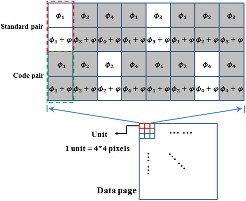
Here, we first studied a four-level phase code-pair encoding method. The diagram of the code-pair encoding method is shown in Fig. 1. In one code-pair, the upper pixel contains encoding phase information. The phase of the upper pixel can be any of these four phases. The phase of the bottom pixel is the sum of the phase of upper pixel and a constant phase shift . Therefore, there is a constant phase difference between the upper pixel and the bottom pixel. Standard code-pairs with known phase information are white blocks distributed uniformly in the data page shown in Fig. 1. Grey blocks are unknown phase code-pairs. If the eight-level phase code-pair method is used, there should be eight standard pairs.

Figure 1.Diagram of the code-pair encoding method.
When the phase interval of the adjacent phase code is larger, it is easier to distinguish different phase codes. Therefore, we set as 0, , , , respectively. The phase interval is . Similarly, if we want to distinguish the phase of the upper pixel and the bottom pixel in one pair more easily, we should set the phase difference between the upper pixel and the bottom pixel as , which means . Therefore, the phase code of two units is shown in Fig. 2. Because the phase distribution exactly meets , , , and , a standard group of four phases can replace four standard pairs in the encoding process. So, the CR can be higher. The calculation formula of the CR is shown as the following: where denotes the number of the phase level. If the four-level phase is used, the CR is one, which is twice the CR of the amplitude code.
Figure 2.Four standard pairs are simplified to one standard group when we use four-level phase 0, , , and , and set the phase shift between the upper pixel and the bottom pixel as .
In the decoding process, a phase-readout reference beam should interfere with the reconstructed beam. In the experiment, the phase difference between the phase-readout reference beam and the reconstructed beam may be not a constant value, which will cause errors, because the relative gray values of different phases will change with the phase difference. The interference results of the background at two different times are shown in Fig. 3. However, in our method, variation of the phase difference will not cause errors because every gray state for one pair of pixels is unique with the change of the phase difference from 0 to . Therefore, we can decode the phase without error. We list some states for one pair of pixels when the phase difference is different, as shown in Fig. 4. The red dot denotes the upper pixel, and the green dot denotes the bottom pixel. The phase difference between the upper pixel and the bottom pixel is . Obviously, there is a unique intensity state for one pair of pixels in one phase period.
Figure 3.Interference between the phase-readout reference beam and the reconstructed beam. Here, the reconstructed beam is not loaded by information. (a),(b) Interference results at different times.
Figure 4.Intensity values of two pixels in one pair with different phase differences between the phase-readout reference beam and the reconstructed beam. The horizontal axis is the phase, and the vertical axis is the intensity value. The red dot denotes the upper pixel, and the green dot denotes the bottom pixel.
When we use a phase-readout reference beam to interfere with the reconstructed beam, we can get an intensity distribution. The intensity values in one unit are shown in Fig. 5. The white block is the standard group corresponding to the standard phase code. Therefore, we can get four standard pairs , , , and . The pairs to be measured are , where . denotes the intensity of the upper pixel, and denotes the intensity of the bottom pixel.
Figure 5.Phase code in one unit and intensity values in one unit after interferometry.
Next, we calculate the intensity variances between the standard pairs and pairs to be measured. Because there are four standard pairs, we get four variance values. The group of formulas is the following: where .
We care about the minimum of these four variances because that means the intensity of the pair to be measured is the closest to a certain standard pair. Then, we assign the phase of the certain standard pair, corresponding to the minimum variance of the pair to be measured.
We use the coupled wave theory for thick hologram gratings and the light wave vector method to simulate the recording process and reading process[20]. In our model, degeneration noise has been considered, which is the main noise caused by Bragg grating mismatch in the reading process[21].
We encode a four-level phase pattern, whose size is 30 by 30, according to the pair code rule. The phase pattern is shown in Fig. 6. The four pixels with different phases in the red frame of Fig. 6 are the standard pixels. The decoding process on this whole image can be performed using the central four pixels as the standard reference.
Figure 6.Four-level phase pattern according to the pair code rule. Four pixels in the red frame are the standard pixels.
When we get the reconstructed beam in the reading process, we use a plane beam with different phases ranging from 0 to as the phase-readout reference beam to interfere with the reconstructed beam to simulate the experimental situation. The bit error rate (BER) curves of the phase retrieval results are shown in Fig. 7. If we do not use the pair code rule and decode the phase by comparing the intensities of unknown pixels and standard pixels, the average BER is about 19%. On the contrary, if we use the pair code rule and decode phases by comparing variances, the average BER is 0.
Figure 7.BER curves of phase retrieval results with and without the pair code rule according to different phase differences between the phase-readout reference beam and the reconstructed beam.
We set up an off-axis holographic data storage system, as shown in Fig. 8, for the experiment. In the writing process, the shutter was open. The reference beam and the signal beam interfered with each other and were recorded in the media. In the reading process, the shutter was closed. Only the reference beam illuminates the media, and the reconstructed beam was read out. Then, another beam called the phase-readout reference beam will interfere with the reconstructed beam, and the interference results shown in Fig. 9 will be captured by the CCD. The wavelength of the laser is 532 nm, and its power is 200 mW. The SLM is a Holoeye-PLUTO-VIS with a pixel pitch of 8 μm and a resolution of 1920 pixel × 1080 pixel. The CCD is a Sony-ICX445 and the pixel pitch of the CCD is 3.75 μm. The focal length of the recording lens is 150 mm. The areal power density in the media is about . The exposure time of the recording is about 6 min. The media is an Irgacure 784-doped polymethyl methacrylate (PMMA) photopolymer with a thickness of 1.5 mm[22].
Figure 8.Diagram of the optical setup. SF, spatial filter; HWP, half-wave plate; BS, beam splitter; , lens; SLM, spatial light modulator. The media is an Irgacure 784-doped PMMA photopolymer with a thickness of 1.5 mm. (, , , pixel pitch of the SLM is 8 μm, the pixel pitch of the CCD is 3.75 μm)
Figure 9.Interference result in the CCD.
We retrieved the phase according to the interference result without and with pair code rule, respectively, and the phase retrieval results are shown in Fig. 10. The original phase pattern is shown in Fig. 10(a), where four pixels in the red frame are the standard pixels. The phase retrieval result without the pair code rule and corresponding phase error distribution are shown in Figs. 10(b) and 10(c). The BER is 25.1%. On the contrary, the phase retrieval result with the pair code rule and corresponding phase error distribution are shown in Figs. 10(d) and 10(e). The BER is 3.3%. We repeated the readout process for nine times. The average BER of situations without the pair code rule is 26.1%, and the average BER of situations with the pair code rule is 4.4%.
Figure 10.Phase retrieval results in the experiment. (a) Original phase pattern. (b) Phase retrieval pattern without the pair code rule. (c) Phase error distribution corresponding to (b). (d) Phase retrieval pattern with the pair code rule. (e) Phase error distribution corresponding to (d).
We propose four-level phase pair encoding and decoding with single interferometric phase retrieval for holographic data storage to increase the data transfer rate. The system in our method is simple, and the robustness is higher. Besides, the CR can reach one, which is twice that of the amplitude code. We demonstrated experimentally there is only a order of BER before error correcting, which is acceptable. The error can be corrected by adding the Bose, Ray-Chaudhuri, Hocquenghem (BCH) error correcting code in the future[23,24]. We believe our method will further advance the phase-modulated holographic data storage technique.
References
[1] H. Horimai, X. Tan, J. Li. Appl. Opt., 44, 2575(2005).
[2] M. Haw. Nature, 422, 556(2003).
[3] H. Horimai, X. Tan. IEEE Trans. Mag., 43, 943(2007).
[4] R. John, J. Joseph, K. Singh. Opt. Lasers Eng., 43, 183(2004).
[5] B. Das, J. Joseph, K. Singh. Opt. Commun., 282, 2147(2009).
[6] G. Berger, M. Dietz, C. Denz. J. Opt. A Pure Appl. Opt., 10, 115305(2008).
[7] M. Takabayashi, A. Okamoto, A. Tomita, M. Bunsen. Jpn. J. Appl. Phys., 50, 09ME05(2001).
[8] M. He, L. Cao, Q. Tan, Q. He, G. Jin. J. Opt. A Pure Appl. Opt., 11, 377(2009).
[9] G. Liu, B. Lu, H. Sun, B. Liu, F. Chen, Z. Zhuang. Chin. Opt. Lett., 14, 071202(2016).
[10] H. Horimai. Asia Communications and Photonics Conference, AF1J.2(2016).
[11] T. Sarkadi, P. Koppa, F. Ujhelyi, J. Reményi, G. Erdei, E. Lörincz. Proc. SPIE, 7000, 700004(2008).
[12] X. F. Xu, L. Z. Cai, Y. R. Wang, X. F. Meng, H. Zhang, G. Y. Dong, X. X. Shen. Opt. Commun., 273, 54(2007).
[13] S. H. Jeon, S. K. Gil. J. Opt. Soc. Korea, 15, 244(2011).
[14] P. Hariharan, B. F. Oreb, T. Eiju. Appl. Opt., 26, 2504(1987).
[15] J. R. Fienup. J. Opt. Soc. Am. A., 4, 118(1987).
[16] V. V. Volkov, Y. Zhu, G. M. De. Micron, 33, 411(2002).
[17] A. M. Maiden, J. M. Rodenburg. Ultramicroscopy, 109, 1256(2009).
[18] R. Horisaki, R. Egami, J. Tanida. Opt. Express, 23, 28691(2015).
[19] J. Zhang, T. Xu, X. Wang, S. Chen, G. Ni. Chin. Opt. Lett., 15, 011702(2017).
[20] H. Kogelnik. Bell Labs Tech. J., 48, 2909(1969).
[21] T. Shimura, S. Ichimura, R. Fujimura, K. Kuroda, X. Tan, H. Horimai. Opt. Lett., 31, 1208(2006).
[22] Y. Liu, F. Fan, Y. Hong, J. Zang, G. Kang, X. Tan. Opt. Express, 25, 20654(2017).
[23] J. A. M. Noriega, B. M. Kurkoski, M. N. Miyatake, H. P. Meana. Int. J. Comput., 5, 26(2011).
[24] C. Desset, B. Macq, L. Vandendorpe. Signal Process. Image Commun., 17, 409(2002).