• High Power Laser and Particle Beams
  • Vol. 32, Issue 4, 045107 (2020)
Xu Wu1、2、3, Shunqiang Tian3, Qinglei Zhang3, and Wenzhi Zhang3
Author Affiliations
  • 1Shanghai Institute of Applied Physics, Chinese Academy of Sciences, Shanghai 201800, China
  • 2University of Chinese Academy of Sciences, Beijing 100049, China
  • 3Shanghai Advanced Research Institute, Chinese Academy of Sciences (Shanghai Synchrotron Radiation Facility, Zhangjiang Laboratory), Shanghai 201204, China
  • show less
    DOI: 10.11884/HPLPB202032.190270 Cite this Article
    Xu Wu, Shunqiang Tian, Qinglei Zhang, Wenzhi Zhang. Operation stability improvement for synchrotron light sources by tune feedback system[J]. High Power Laser and Particle Beams, 2020, 32(4): 045107 Copy Citation Text show less

    Abstract

    Ten Insert Devices (IDs) had been installed in the Shanghai Synchrotron Radiation Facility (SSRF) storage ring. The ID gaps were repeatedly adjusted for the scientific experiments during the user time. The residual quadrupole errors beyond the ID feedforward disturbed the beam optics, including the betatron tune deviations that spoiled machine performance and brightness stability. A tune feedback system was developed and implemented in the SSRF storage ring to resolve the deterioration. The tune stability of ±0.001 in 2 weeks was reached. Another important function of this feedback system is finding out slow drift in the power supplies of dipole or quadrupole by observing the correction current changes in the feedback. To prove this feedback’s feasibility, we compared variations of the beam parameters, including the injection efficiency, the beam life-time, the horizontal beam size and the beta-beatings.

    This paper is organized as follows. Section 1 mainly describes the tune variation in the SSRF storage ring. Section 2 introduces the algorithm and the main functions of the tune feedback system. The operation results of this feedback are presented in Section 3 and several important beam parameters in storage ring before and after using the feedback are compared and discussed. Section 4 presents the conclusions.

    Plane polarization IDs and Elliptical Polarization Undulators (EPU) are widely applied as radiation emitter in the synchrotron radiation facilities[3]. Some novel types of IDs are also interesting in scientific experiments and have been installed in the light sources. While a single plane polarization ID makes little contribution to tune deviations, summation of many IDs is significant when they are operated simultaneously[1]. For EPUs, feedforward by the adjacent quadrupoles is an appropriate method to suppress the beam optics distortions[5], while the residual effects are obvious in many cases.

    In order to improve the tune stability, we developed a betatron tune feedback system that was implemented in SSRF. The tune stability in either horizontal or vertical direction within the feedback in operation about 2 weeks reached in a range of ±0.001. Another important function of this feedback system is finding out any slow drift in the power supplies of dipole or quadrupole by observing the correction current changes in the feedback. To prove this feedback feasibility, we compared the beam parameter variations, including the injection efficiency, the beam life time, the horizontal beam size and the beta-beatings, with and without this feedback system.

    Synchrotron radiation facilities provide highly stable and bright photon beam for user’s experiments. Besides closed orbit stability, betatron tune stability is also important to stabilize the photon brightness[1], mainly for three reasons. The first reason is that the tune deviation intrinsically means beam optics distortions and beam emittance variation. Along with the brightness instability, the beam life time and injection efficiency in the top-up operation will reduce because of the dynamic aperture’s change which comes from the beam optics distortions[2]. The second reason is that the tunes possibly cross dangerous nonlinear resonances and the third one is that the transverse feedback system will be disabled, when the tune deviates a lot. Both the latter two will intensify beam oscillation, even to cause beam loss. The tune deviations are mainly resulted from the mismatched rf frequency, the power supply drifts of dipoles and quadrupoles, and the quadrupole errors in Insert Devices (IDs)[2-3]. Correct control of the rf frequency is easy within soft orbit feedback[4], while that of the drifts and the errors need other passive compensation method[5].

    1 Tune variation in the SSRF storage ring

    SSRF is a 3rd generation synchrotron radiation light source that has been in operation with high brightness for ten years[6]. SSRF consists of a 150 MeV electronic linear accelerator, a 150 MeV−3.5 GeV synchrotron booster and a 3.5 GeV storage ring[7]. The circumference of the storage ring is 432 m, including twenty double-bend achromat (DBA) cells, each of them contains two bending magnets and ten focusing and defocusing quadrupoles[8]. There is a total of four long straight sections of 12 m and sixteen standard straight sections of 6.5 m in the storage ring. Two of the long straight sections are used for the installation of injection system and for the installation of RF cavities respectively, and the other 18 sections are all used for the installation of IDs (undulators, wigglers, etc.). The detailed beam parameters are summarized in Table 1, including the designed values and the measured values.

    parameterdesign valuemeasured value
    beam energy / GeV3.503.50
    circumference / m432---------
    number of cells20---------
    constructionDBA---------
    numbers of QF/QD in one cell4/6---------
    beam current / mA200−300240
    tune (H, V)22.22, 11.2922.220, 11.290 (±0.01)
    natural emittance / nm·rad3.893.9
    coupling1%0.3%
    natural chromaticity (H, V)−55.7, −17.9--------
    corrected chromaticity (H, V)---------1.5, 2.5
    RMS energy spread9.845×10−40.001
    energy loss per turn / MeV1.435~1.45
    momentum compaction factor4.27×10−44.2 ×10⁻⁴
    RF voltage / MV4.04~4.8
    RF frequency / MHz499.654499.68
    synchrotron frequency0.007 20.007 5

    Table 1. Beam parameters of the SSRF storage ring

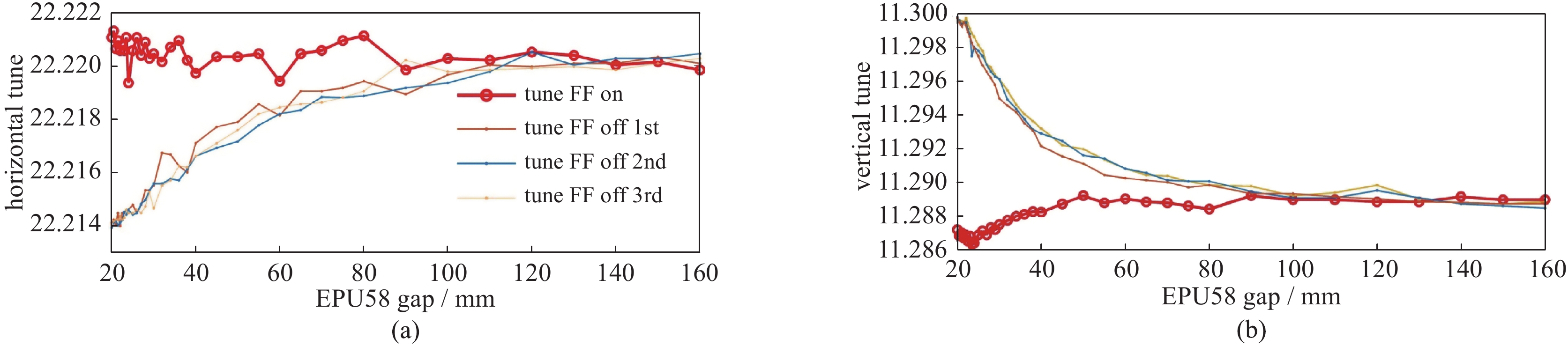
    In the SSRF storage ring, the slow and fast orbit feedback systems (SOFB & FOFB) are in operation to make the closed orbit stable and the transverse feedback system stabilizes the beam size. At present, ten IDs have been installed in the SSRF storage ring, including two wigglers, three EPUs, and five In-Vacuum Undulators (IVUs). EPU58 has a much larger effect on the tunes than the other IDs, hence a feedforward system adopting ten adjacent quadrupoles as the correction elements has been established and operated in SSRF [5]. The performance of this feedforward is shown in Fig. 1. The red line that marked with circles represents the situation when the feedforward was turned on, while the other three lines represent the cases when the feedforward was turned off. Before each test, the gap of EPU58 was pulled to the maximum (160 mm) and the tunes were adjusted close to the designed values (22.220/11.290). In the test, the gap of the EPU58 was gradually adjusted from the maximum value to the minimum (20 mm) while the variations of the tunes were recorded.

    Tune feedforward effects

    Figure 1.Tune feedforward effects

    As shown in Fig. 1, within the gap from 160 mm to 20 mm, the tune deviations are reduced from −0.006/0.01 to 0.002/−0.001 (horizontal/vertical) by the feedforward compensation. Although the compensation effect for tunes is obvious, the residual errors over the feedforward still exist. On the other hand, the gaps of all the IDs were adjusted repeatedly within the allowable range, and the summation of the effects on the tune variation was significant when they were operated simultaneously.

    The quadrupole disturbances in the global storage ring are unpredictably, and the effect on the beam optics is not obvious in a short period. However, during about 2 weeks’ operating period, the repeated accumulation of the quadrupole errors might result in a significant change in the beta-functions and the betatron tunes, which might further lead to a reduction in beam life time and injection efficiency, as well as changes in the transverse horizontal beam size which in turn leads to the instability of the synchrotron radiation light[9-11].

    2 Establishment of the tune feedback system

    2.1 Tune Feedback Algorithm

    The software of the tune feedback system is Accelerator Toolbox (AT)[12], which is used to construct the SSRF storage ring lattice and simulate the feedback.

    In accelerators, the betatron tunes are defined as the number of the beam oscillations in one cycle. Differential of the phase advance (or tune) is proportional to 1/β. The relationship between the β-function and the quadrupole magnetic field strength (K) and the relationship between the tune variations and the change of K are described by Eq. (1) and Eq. (2) respectively[3]

    $ 2\beta \beta ' - {\beta '^2} + 4{\beta ^2}K = 4 $

    $ \Delta {v_{x,y}} = \frac{1}{{4{\text{π}} }}\oint {{\beta _{x,y}}\left( s \right)\delta K\left( s \right)\text{d}s} $

    where β presents the β-function with the unit of m, and the subscript x and y represent the horizontal and vertical directions, respectively. The unit of K is m-1. ∆νx,y is the tune variations in horizontal and vertical planes, while δK(s) is the change of the quadrupole magnetic field at the position s. In the tune feedback design of the SSRF storage ring, the quadrupoles in the existing lattice are directly used as the correction elements.

    The algorithm used in the feedback is based on Response Matrix method (RM) and Singular Value Decomposition method (SVD)[13-15]. At first, the RM of the tunes to each quadrupole in the storage ring was calculated, then a matrix (M) with 2 rows and 200 columns was constructed by these elements. The inverse matrix of −M−1 was obtained by SVD method. If the variation vector of the tune is $\Delta {v_{x,y}} = {\left[ {\begin{array}{*{20}{c}}{\Delta {v_x}}&{\Delta {v_y}}\end{array}} \right]^\prime }$, the adjusted current ∆IFB with 200 rows and 1 column required for each quadrupole is calculated by Eq. (3), which can correct the tunes to the target values.

    $ \Delta {I_{{\rm{FB}}}} = {\left[ {\begin{array}{*{20}{c}} {\Delta {I_1}}&{\Delta {I_2}}&{ \cdots \cdots }&{\Delta {I_{200}}} \end{array}} \right]^\prime } = - {M^{ - 1}} \cdot {\left[ {\begin{array}{*{20}{c}} {\Delta {v_x}}&{\Delta {v_y}} \end{array}} \right]^\prime } $

    Each quadrupole current variable was added to the corresponding quadrupole magnet power supply, thus completed a tune feedback correction loop. It is also important to note that the current corrections need to be multiplied by a coefficient f between 0 and 1 which prevents excessive correction. In the practice, we found that it was appropriate to take the value of about 0.7. However, our feedback program can adjust the coefficient momentarily by judging the value of the current tune variable.

    The beam spectrum analysis method, whose measurement resolution is better than 0.000 02 when betatron motion is generated by injection kickers, was used to measure the transverse betatron tunes in SSRF storage ring[16]. SSRF is now in operation with the top-up injection[17], the betatron tunes can be precisely measured when beam injection occurs. Thus, the working frequency of the feedback is the same as the frequency of the top-up injection, which is one shot in about every five minutes.

    2.2 Feedback type and optimal choice

    Fig. 2 shows the linear beam optics and the lattice layout of one cell in the SSRF storage ring. In Fig.2(a), the blue line, the red line, and the green line represent the horizontal beta function, the vertical beta function and the 50 times of the horizontal dispersion, respectively, and the horizontal axis represents the longitudinal coordinates of the storage ring. Fig.2(b) shows the lattice layout, where we’ve marked three types of magnets that consist of dipoles, quadrupoles and sextupoles. Each cell in the storage ring includes ten quadrupoles (four focusing quadrupoles and six defocusing quadrupoles), and all the 200 quadrupoles in 20 cells can be used as correction elements for the tune feedback system. To maintain global symmetry and uniformity, at least two pairs of focusing and defocusing quadrupoles are necessary in the tune feedback system.

    Beam optics and lattice for a cell

    Figure 2.Beam optics and lattice for a cell

    In this situation, there are 16 types of quadrupole combination modes available for the tune feedback. We mark the used and unused quadrupoles by 1 and 0, respectively, e.g., mode M11000 (abbreviated from the symmetrical M1100000011) means to select the 1st, 2nd, 9th, and 10th quadrupole in each cell to correct the tune deviations. Before the feedback was put into operation, we simulated the 16 combination modes and evaluated the corresponding operation effects. The sensibility of the magnets to the betatron tunes was also considered as an evaluation[18]. The simulation results showed three modes, including M11000, M11100 and M11111, had better performances.

    2.3 Magnet power supply monitor

    To prevent the feedback failure due to excessive current changes, the quadrupole power supplies were monitored all the time when the tune feedback was running. A single correction of the magnet power supply was limited to less than 0.1 A, while the accumulated correction and the RMS value were constrained within 0.8 A and 0.5 A respectively. Another important function of the feedback current monitor system is to determine whether there is a slow drift in any power supplies of dipole or quadrupole in the storage ring by observing the changing trend of the current correction.

    All the 40 dipoles in the SSRF storage ring are powered by one supply. If the power supply presents slow drift without correction, the actual bending field usually and unconsciously continues to decrease, resulting in more focus in both horizontal and vertical directions because of the lower beam energy. The most direct phenomenon is that the betatron tune will continue to grow. Since the absolute value of natural horizontal chromaticity is larger than the vertical one[19], the horizontal tune is changed more than the vertical one.

    In the SSRF storage ring, all the 200 quadrupoles are powered by independent power supplies. If any one of the quadrupoles has slow drift, the focus in both transverse planes will change, which can lead the betatron tunes shift. The feedback makes a responding correction, and then the power supplies that participate in the feedback will show monotone changes. After several hours or days of accumulation, the changing trend of the correction current will be quite obvious.

    We tested slow drift in dipole and quadrupole on the machine. The feedback results are shown in Fig. 3, where the vertical axes represent the feedback current changes, and the horizontal coordinates represent the correction steps. The red lines represent four families of focusing quadrupoles, and the green lines indicate the current change of the defocusing quadrupoles. The test results are fully consistent with the analysis of the previous paragraph, so it can be used to determine whether the power supplies have a slow drift.

    Correction currents and magnets drift

    Figure 3.Correction currents and magnets drift

    3 Stable operation of tune feedback

    3.1 Improvement of the tune stability

    The tune feedback system with the mode M11100 has been implemented in SSRF since March 20, 2019. Tune variations, when running the feedback system, have been recorded during the operation for users’ experiments. The results within 4 weeks are shown in Fig. 4, along with the results within 8 weeks without the tune feedback. The horizontal axis in Fig.4(a) and (b) showed the number of records. The plots in Fig.4(a) and (b) are for horizontal tune and the vertical tune, respectively. In this two plots, a vertical dotted line was added to divide the recorded values into two parts, of which the left part represents the tune variations without the tune feedback (8 weeks, November 20, 2018~2019 March 19) and the right part represents the variations with the feedback (4 weeks, March 20−April 15, 2019). In these days, the tune feedforward of the EPU58 was always tuned on.

    Stable operation of tune feedback

    Figure 4.Stable operation of tune feedback

    Fig.4(c) plots the tunes with the resonance lines together. The red line in the figure represents a regular seventh order resonance line and the blue one represents a regular eighth and a skew fourth order resonance line, and the green one is the regular fifth order line and the yellow lines are the ninth resonance lines. At the same time, the black gracile lines are the tenth order lines. The tunes before using feedback are plotted with pink dots and those corrected by tune feedback system are represented by green points, and the target tune is plotted by a red dot. It is clear that the tunes before using the feedback system cross some resonance lines. This may be one reason for beam oscillation. Attributed to the feedback system, the variation range of tunes are much smaller than before.

    During the four-week operation within the tune feedback, the target tune of the first two weeks were the one corrected by the Linear Optics from Closed Orbit (LOCO)[20-21]. However, the correcting effects from LOCO are not so identical that there are some differences among tunes after every LOCO correction. From the last two days of the second week (about 24 000 points in the corresponding figure), we ran the feedback system with the tune targets as same as the designed ones (22.22/11.29)[8]. As a result, there are several steps in the Fig. 4(a) and (b). Before the start of each operation period, it is necessary to use LOCO to correct the tunes to be close to the designed values. The correction has the following benefits: 1) reaching long-term tune stability, 2) minimizing the deviation of beam optics between machine and model from the beginning.

    Improvement of the tune stability is very clear in Fig. 4. When there was no tune feedback, the tunes varied from 22.206 8 to 22.256 5 in the horizontal plane, and from 11.287 9 to 11.317 9 in the vertical plane. In this large range, there were several resonances that the beam had crossed. It is fortunate not to cause beam loss, while some instabilities were indeed observed, such as drop in beam life time and beam size growth. After the tune feedback system was put into operation, the mean values of the tunes were 22.220 3 in horizontal plane and 11.289 7 in vertical plane respectively, and the varying ranges are from 22.215 3 to 22.225 7 in horizontal plane and from 11.286 6 to 11.295 0 in vertical plane. The RMS values had reached 0.000 3% and 0.000 1% in horizontal and vertical planes, respectively.

    3.2 Beta-beatings

    In order to estimate the influence of tune feedback on beam optics, we mainly studied four beam parameters—the horizontal beam size, the injection efficiency, the beam life time and the beta-beatings (βbeat) before and after the use of feedback. The following analysis will illustrate that this tune feedback system is feasible because it doesn’t have bad effect on these beam parameters.

    Firstly, we compare the beta-beatings before and after the use of the tune feedback. The beta-beatings are calculated from βbeat=(βLOCOβmodel)/βmodel, where βLOCO is the beta function obtained from a fitted model by LOCO and βmodel is the designed one. Fig.5 shows the beta-beatings, the plot in (a) and (c) is the one without the tune feedback, while (b) and (d) show the results with the tune feedback. The red, blue, and green lines in Fig. 5 show data of three measurements, which were carried out with a one-week interval. For the cases with the tune feedback, it means that the feedback lasted for a week.

    Beta-beatings

    Figure 5.Beta-beatings

    The RMS beta-beatings without tune feedback, measured a week after the LOCO correction, are about 3% in horizontal plane and 1% in vertical plane. In ideal condition, the tunes can be corrected very well and the beta-beatings can be simultaneously suppressed, if all the quadrupoles in the storage ring are adjusted to match the beta functions to the designed model. However, the beta functions cannot be accurately or quickly measured without affecting users’ experiments. In our tune feedback system, only the measured tunes were the objectives for correction, not considering the beta function, the beta-beatings in both transverse planes, measured a week after LOCO correction, did not aggravate. The RMS beta-beatings reached 1.0% and 1.5% in horizontal and vertical planes respectively.

    3.3 Beam parameter variations

    Fig. 6 plots the variations of the horizontal beam size, the injection efficiency, and the beam lifetime within the same operation periods described in Section 2, i. e. 8 weeks without the tune feedback, and 4 weeks with feedback. The stability improvements for these parameters are also obvious. The horizontal beam size varied from 68 μm to 80 μm in the eight weeks without the tune feedback. If ignoring the mutational part (about No. 32000), the peak-to-peak variation ratio was even about 10.8%. During the weeks of using tune feedback, the ratio was about 6.8% (from 70 μm to 75 μm). The injection efficiency before tune feedback implementation varied from 40% to 100%, while it was stabilized above 90% by the tune feedback. The beam lifetime variation range was reduced to two hours from about ten hours. These comparisons show that the main beam parameter stabilities of the SSRF storage ring obtained great improvements with the tune feedback system.

    Main beam parameter variations

    Figure 6.Main beam parameter variations

    4 Conclusion

    A tune feedback system was established and has been implemented in the SSRF storage ring since March, 2019. The system made the storage ring achieve a tune stability of 0.001 in both transverse planes, and reach accepted RMS beta-beatings of about 1.0% in the horizontal plane and 1.5% in the vertical plane. The quadrupole current correction monitor in this feedback system can also be used to find out any slow drift in dipole and quadrupole power supplies. This function provides a pre-judgment for the power supply failures in the SSRF operation. The main beam parameters of the storage ring were compared between before and after using this tune feedback system. Great improvements for these beam parameter stabilities were achieved, which proves that this tune feedback system is feasible.

    References

    [1] Heron M T, Abbott M G, Furseman M, et al. Feedfward feedback schemes applied to the diamond light source stage ring[C] Proceedings of IPAC2014, 2014: 17571759.

    [2] Martin I P S, Fielder R, Furseman M, et al. Active optics stabilisation measures at the diamond stage ring[C]Proceedings of IPAC2014, 2014: 17601762.

    [3] Chao A W, Mess K H, Tigner M, et al. Hbook of accelerat physics engineering[M]. 2nd ed. Wld Scientific, 2013.

    [4] Hou Jie, Tian Shunqiang, Zhang Manzhou. Studies of closed orbit correction and slow orbit feedback for the SSRF storage ring[J]. Chinese Physics C, 33, 145-150(2009).

    [5] Zhang Manzhou, Wang kun, Zhang Qinglei. Compensations of double elliptical polarization undulator effects on the SSRF storage ring[J]. High Power Laser and Particle Beams, 29, 075103(2017).

    [6] Tian Shunqiang, Zhang Manzhou, Zhang Qinglei, et al. Lattice design of the SSRFU stage ring[C] Proceedings of IPAC2015, 2015: 304306.

    [7] Dai Zhimin, Liu Guimin, Huang Nan. Design of the SSRF storage ring magnet lattice[J]. Nuclear Science and Techniques, 14, 89-92(2003).

    [8] Zhang Wenzhi, Tian Shunqiang, Zhang Manzhou. Design and first commissioning of a new mode with lower emittance in the SSRF storage ring[J]. Chinese Physics C, 33, 397-400(2009).

    [9] Tomás R, Aiba M, Franchi A. Review of linear optics measurement and correction for charged particle accelerators[J]. Physical Review Accelerators and Beams, 20, 054801(2017).

    [10] Tian Shunqiang, Zhang Wenzhi, Li Haohu. Linear optics calibration and nonlinear optimization during the commissioning of the SSRF storage ring[J]. Chinese Physics C, 33, 83-85(2009).

    [11] Tian Shunqiang, Hou Jie, Chen Guangling. Analysis of sextupole effects on β function beating in the SSRF storage ring[J]. Chinese Physics C, 32, 576-579(2008).

    [12] Terebilo A. Accelerat modeling with MATLAB[C] Proceedings of the 2001 Particle Accelerat Conference, 2001: 32033205.

    [13] Chen, Jianhui, Zhang Manzhou, Zhao Zhentang. Orbit response matrix analysis and lattice periodicity restoration of the SSRF storage ring[J]. Chinese Physics C, 33, 785-788(2009).

    [14] Safranek J. Experimental determination of storage ring optics using orbit response measurements[J]. Nuclear Instruments and Methods in Physics Research A, 388, 27-36(1997).

    [15] Liu C, Hulsart R, Michnoff R, et al. Weighted SVD algithm f closedbit crection 10Hz feedback in RHIC[C]Proceedings of IPAC2012, 2012: 29062908.

    [16] Leng Yongbin, Yan Yingbing, Yuan Renxian. Betatron tune measurement system for Shanghai Synchrotron Radiation Facility storage ring[J]. High Power Laser and Particle Beams, 22, 2412-2416(2010).

    [17] Zhao Zhentang, Yin Lixin, Zhang Wenzhi, et al. Progress towards topup operation at SSRF [C] Proceedings of IPAC2011, Spain, 2011: 30083010.

    [18] Jena S, Yadav S, Agrawal R K. Stabilization of betatron tune in Indus-2 storage[J]. Chinese Physics C, 38, 067002(2014).

    [19] Tian Shunqiang, Hou Jie, Chen Guangling. New chromaticity compensation approach and dynamic aperture increase in the SSRF storage ring[J]. Chinese Physics C, 32, 661-664(2008).

    [20] Safranek J, Ptmann G, Terebilo A. MATLABbased LOCO[C] The 8th European Particle Accelerat Conference, 2002.

    [21] Zhou Xuemei. Measurement of optics for the SSRF storage ring in commissioning[J]. Chinese Physics C, 33, 78-82(2009).

    Xu Wu, Shunqiang Tian, Qinglei Zhang, Wenzhi Zhang. Operation stability improvement for synchrotron light sources by tune feedback system[J]. High Power Laser and Particle Beams, 2020, 32(4): 045107
    Download Citation