
Yun-Long Ling, Chuan Wang, Hai-Chao Zhang. Three wires ring magnetic guide based on Archimedean spirals [J]. Acta Physica Sinica, 2020, 69(10): 100301-1
- Acta Physica Sinica
- Vol. 69, Issue 10, 100301-1 (2020)
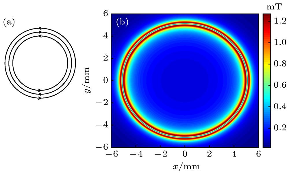
Fig. 1. (a) The ideal structure of the three concentric ring wires. The arrows represent the direction of currents; (b) The magnetic field intensity distribution of the ideal ring magnetic guide. The blue circle marks the ring magnetic guide.
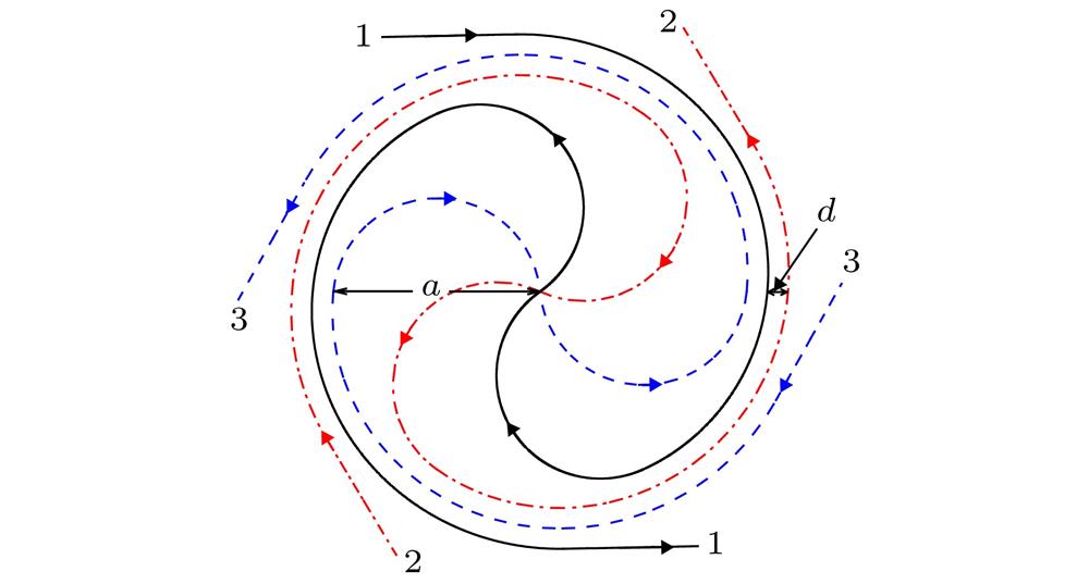
Fig. 2. Archimedean-spiral-based three wires structure of the ring waveguide. The black solid line, the red chain-dotted line and the blue dashed line denote three different wires respectively. The input and output ports of each wire are marked by 1, 2, 3 and the arrows represent the direction of currents. The initial radius of Archimedean spirals is
 and the distance between neighboring spirals is
 .
.
and the distance between neighboring spirals is
. Fig. 3. The relation of the angular magnetic field intensity
 of the guide center with the modulation depth
 when the modulation frequency is
 , the current phase is
 and the DC part of the currents is
 . When the modulation depth is
 , the variation of the angular magnetic field intensity is the minimum:
 .
.
of the guide center with the modulation depth
when the modulation frequency is
, the current phase is
and the DC part of the currents is
. When the modulation depth is
, the variation of the angular magnetic field intensity is the minimum:
. Fig. 4. The distribution of the magnetic field intensity in the
 cross section of the ring magnetic guide generated by the Archimedean-spiral-based three wires structure. The DC part and the AC part of the modulation currents are
 and
and
 , respectively. The modulation frequency is
 . The current phase is
 . After loading AC modulation, the minimum (zero point) of the magnetic field rotates along the red dashed line. The variation amplitude of the path along
 r and z direction are respectively
 and
and
 .
.
cross section of the ring magnetic guide generated by the Archimedean-spiral-based three wires structure. The DC part and the AC part of the modulation currents are
and
, respectively. The modulation frequency is
. The current phase is
. After loading AC modulation, the minimum (zero point) of the magnetic field rotates along the red dashed line. The variation amplitude of the path along and
. Fig. 5. (a) The magnetic field distribution in the cross section with
 of the ring magnetic guide along
 r direction before (black solid line) and after (red dashed line) loading AC modulation; (b) The magnetic field distribution in the cross section with
 of the ring magnetic guide along
 z direction before (black solid line) and after (red dashed line) loading AC modulation. The DC part and the AC part of the AC modulation currents are
 and
and
 , respectively. The modulation frequency is
 . The current phase is
 . After loading AC modulation, the minimum of the magnetic field intensity in the cross section changes from
 to
to
 .
.
of the ring magnetic guide along of the ring magnetic guide along and
, respectively. The modulation frequency is
. The current phase is
. After loading AC modulation, the minimum of the magnetic field intensity in the cross section changes from
to
. Fig. 6. The magnetic field intensity of the guide center versus azimuthal angle
 for loading DC currents only (dashed line) and loading AC modulation (solid line), respectively. The dashed line: The DC currents applied to the three wires respectively are
 ,
,
 ,
,
 . The variation of the magnetic field is about
 . The difference between the maximum and the minimum is
 . The solid line: The DC part and the AC part of the AC modulation currents applied to the three wires are
 and
and
 , respectively. The modulation frequency is
 . The current phase is
 . The magnetic field intensity of the guide center is about
 . The variation of the magnetic field is
 .
.
for loading DC currents only (dashed line) and loading AC modulation (solid line), respectively. The dashed line: The DC currents applied to the three wires respectively are
,
,
. The variation of the magnetic field is about
. The difference between the maximum and the minimum is
. The solid line: The DC part and the AC part of the AC modulation currents applied to the three wires are
and
, respectively. The modulation frequency is
. The current phase is
. The magnetic field intensity of the guide center is about
. The variation of the magnetic field is
. Fig. 7. Applying AC modulation to the three-wires Archimedean spirals structure. The DC part and the AC part of the AC modulation currents are
 and
and
 , respectively. The modulation frequency is
 . The current phase is
 . (a) and (b) are respectively the spatial position in
 r direction and z direction of the ring magnetic guide after loading AC modulation. The amplitudes of variation along r direction and z direction are
 and
and
 , respectively.
and
, respectively. The modulation frequency is
. The current phase is
. (a) and (b) are respectively the spatial position in and
, respectively. Fig. 8. The magnetic field intensity distribution of the three-wires Archimedean spirals structure of the ring magnetic guide at
 when both DC and AC modulation are loaded. The blue circle marks the ring magnetic guide and the magnetic field intensity of the guide center is about
 . The DC part and the AC part of the currents are
 and
and
 , respectively. The modulation frequency is
 . The current phase is
 .
.
when both DC and AC modulation are loaded. The blue circle marks the ring magnetic guide and the magnetic field intensity of the guide center is about
. The DC part and the AC part of the currents are
and
, respectively. The modulation frequency is
. The current phase is
. 
Set citation alerts for the article
Please enter your email address
© Copyright 2018-2021 | Chinese Laser Press. All Rights Reserved 沪ICP备15018463号-20