Author Affiliations
1School of Physics and Optoelectronic Engineering, Foshan University, Foshan 528000, China2Department of Physics, Collaborative Innovation Center for Optoelectronic Semiconductors and Efficient Devices, and Jiujiang Research Institute, Xiamen University, Xiamen 361005, Chinashow less
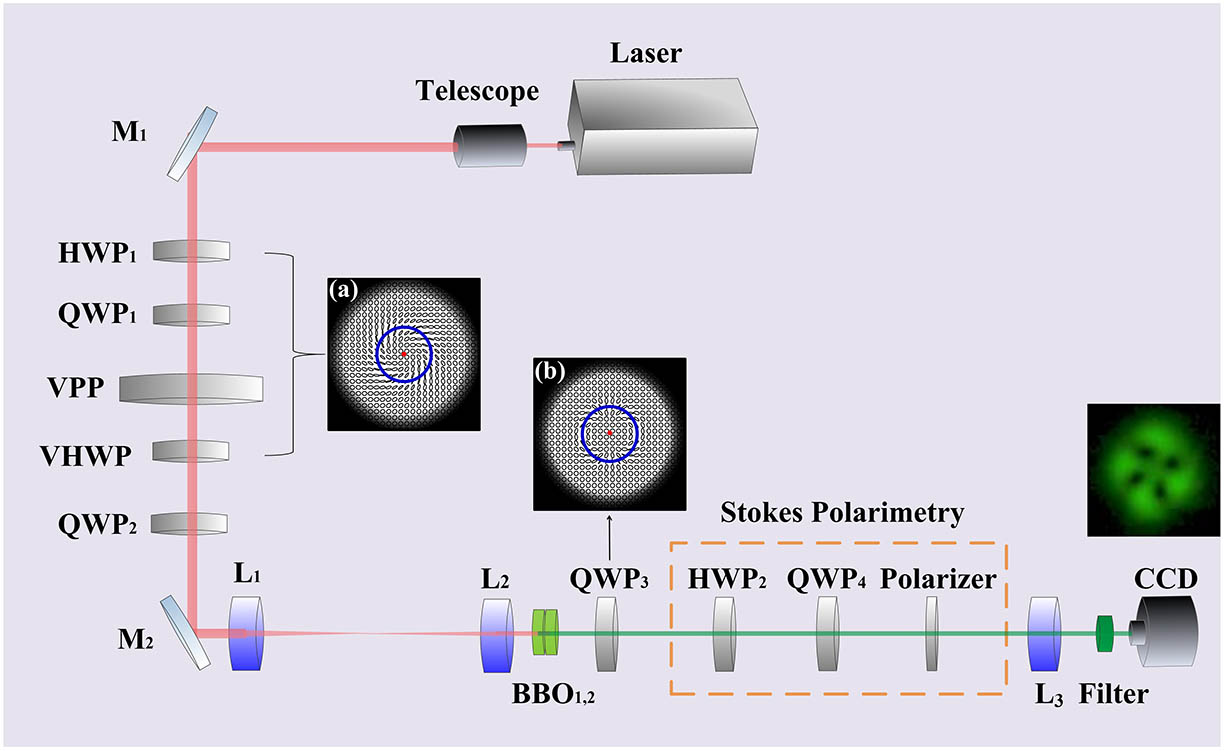
Fig. 1. Experimental setup for SHG of FP beams in BBO crystals.
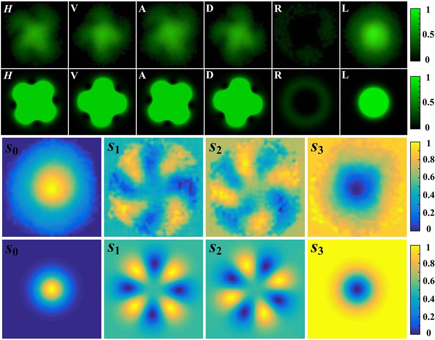
Fig. 2. Polarization and Stokes components for an output SHG light field with . The first and second rows show the experimental and theoretical results for the six polarization components, respectively. The third and fourth rows show the experimental and theoretical Stokes components, respectively.
Fig. 3. Polarization and Stokes components for an output SHG light field with . The first and second rows show the experimental and theoretical results for the six polarization components, respectively. The third and fourth rows show the experimental and theoretical Stokes components, respectively.
Fig. 4. Polarization distribution of SHG beams with 532 nm at , 15°, 30°, 45°, 60°, 75°, 90°. Top panel, numerical simulations of the polarization distribution of fundamental beams; middle panel, numerical simulations of the polarization distribution of SHG beams; bottom panel, experimental results of the polarization distribution of SHG beams.
Fig. 5. Streamlines around C points at . (a) Numerical result for fundamental FP beam; (b) and (c) numerical and experimental results of the SHG FP beam, respectively. Blue lines and red points denote the L lines and C points, respectively.
| States |
---|
Elements | H | V | A | D | R | L |
---|
| – | – | 22.5° | 22.5° | – | – | | – | – | – | – | 45° | 45° | Polarizer | 0° | 90° | 0° | 90° | 0° | 90° |
|
Table 1. Settings of the Optical Elements in the Setup to Detect the States of Polarization