
Tianyu Shao, Jianqiang Gu, Wenqiao Shi. Automated Design Study of Guided-Mode Resonance Filters Working at Terahertz Frequencies[J]. Chinese Journal of Lasers, 2021, 48(20): 2014001
- Chinese Journal of Lasers
- Vol. 48, Issue 20, 2014001 (2021)
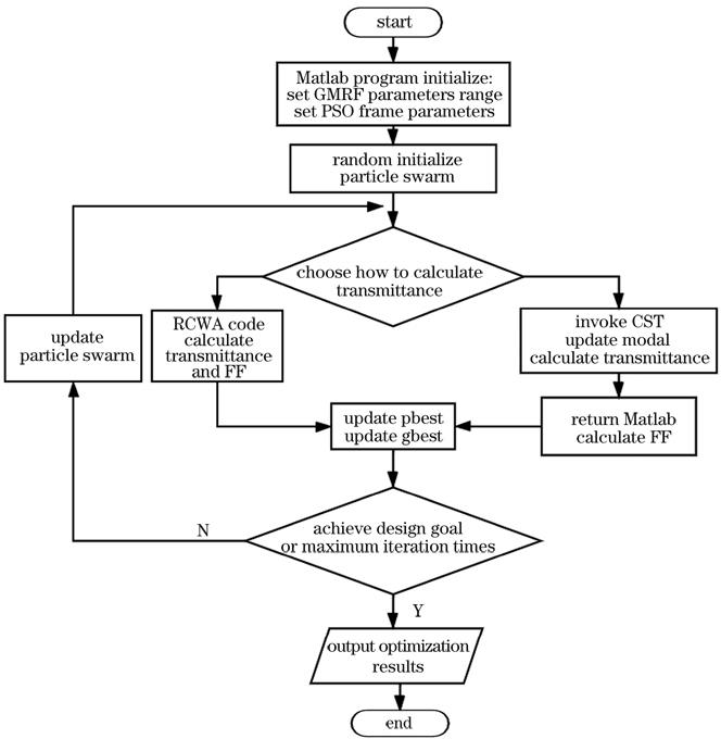
Fig. 1. Flowchart of the automated design of guided mode resonance filters
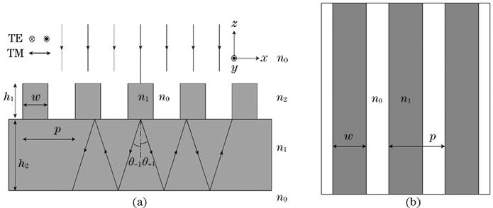
Fig. 2. Schematic diagram of the silicon grating under normal incidence. (a) Schematic diagram of cross section; (b) top view of the grating
Fig. 3. Transmission and electromagnetic field distributions of silicon grating. (a) Transmission of silicon grating calculated by CST under TE polarization; (b) transmission of silicon grating calculated by CST under TM polarization; (c) transmission of silicon grating calculated by RCWA under TE polarization; (d) transmission of silicon grating calculated by RCWA under TM polarization; (e) electric field distribution of Fig. 3 (a) at 0.6522 THz; (f) magnetic field distribution of Fig. 3 (a) at 0.6522 THz
Fig. 4. Schematic and design result of the metasurface grating. (a) Three-dimensional view; (b) square cell structure; (c) transmission distribution between 0.55 THz and 0.65 THz; (d) cross section electric field distribution at 0.6 THz
Fig. 5. Photographs of silicon grating sample. (a) Photograph of silicon grating; (b) SEM of the central sample
Fig. 6. 8F terahertz time domain spectroscopy system. (a) Terahertz beam path diagram; (b) picture of experimental facility
Fig. 7. Measurement results of the central sample of silicon grating. (a) Time domain THz signal; (b) its corresponding amplitude spectrum; (c) comparison between simulation results (dot line) and experimental results (solid line)
Fig. 8. Influence of size error on the resonance frequency. (a) Influence of horizontal error; (b) influence of depth error
Fig. 9. Spectra of the silicon grating at 0°, 4°, and 8° incident angles. (a) Simulation result; (b) experimental results
|
Table 1. Parameters and resonance frequencies of the gratings optimized by CST and RCWA

Set citation alerts for the article
Please enter your email address
© Copyright 2018-2021 | Chinese Laser Press. All Rights Reserved 沪ICP备15018463号-20