
Jia JIANG, Minming GENG, Qiang LIU, Zhenrong ZHANG. Design of a Reconfigurable Optical Filter Based on Triple-ring-assisted Mach-Zenhnder Interferometer with Large Bandwidth Tuning Capability[J]. Acta Photonica Sinica, 2021, 50(7): 275
- Acta Photonica Sinica
- Vol. 50, Issue 7, 275 (2021)
Abstract
Keywords
0 Introduction
In the past decades, especially in the twenty years of the new century, the silicon photonics has been developing extremely rapidly, due to its superiorities in many aspects, such as fabrication technology, integration density, excellent performance, application diversity and so on[
1 Selection and optimization of scheme
As mentioned above, there are mainly two kinds of schemes to design the bandwidth-tunable optical filter. One is based on ring-assisted MZI, the other is based on multiple cascaded microring resonators. The performance parameters of the optical filters based on the two schemes are summarized in Table 1. The BTRs of the two schemes are almost the same. But in general, the filters based on ring-assisted MZI have an edge in terms of the proportion of BTR in the whole FSR, which is more suitable for designing optical filter with large BTR. Thus, the scheme based on ring-assisted MZI is selected in this paper.
| Scheme | BWmax / FSR | Tunable BW / nm | Ref. |
|---|---|---|---|
| MRRs in an MZI | 0.88 nm / 9 nm | 0.46~0.88 | [ |
| MRRs in an MZI | 1.44 nm / 1.6 nm | 0.16~1.44 | [ |
| MRRs in an MZI | 1.12 nm / 8.5 nm | 0.37~1.12 | [ |
| MRRs in an MZI | 0.113 nm / 0.256 nm | 0.033~0.113 | [ |
| Cascaded rings | 1 nm / 7.2 nm | 0.0928 ~1 | [ |
| Cascaded rings | 1.2 nm / 70.8 nm | 0.3~1.2 | [ |
| Cascaded rings | 0.16 nm / 16 nm | 0.12~0.16 | [ |
| Cascaded rings | 0.64 nm / 1.8nm | 0.056~0.64 | [ |
Table 1. The summarization of performance of different schemes
To meet the requirements of optical fiber communication systems[
2 Theoretical analysis and optimization of key parameters
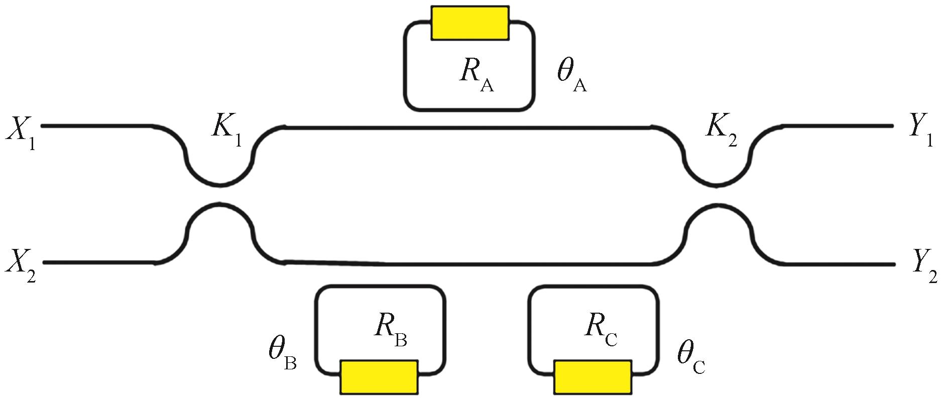
The structure of the designed optical filter, which is based on triple-ring-assisted MZI, is shown in Fig.1. The inputs are denoted by X1 and X2, and the outputs are denoted by Y1 and Y2. X2 is zero during the process of design and simulation. The power coupling ratios of the 3-dB couplers named K1 and K2 are k1 and k2, respectively. The three MRRs are the key phase control units in the filter. The MRR called RA is coupled with the upper arm of the MZI, and RB as well as RC is coupled with the lower arm. Thus, the structure of the optical filter is asymmetric, which makes the bandwidth of the filter can be tuned. In order to control the coupling strength and phase conveniently, the race-track structure is selected. The three yellow areas in Fig.1 are used to change the phases of the MRRs, named θA, θB and θC, respectively, to tune the center wavelength of the optical filter by thermo-optic or electro-optic effect of silicon[
![]()
Figure 1.Schematic of the proposed device based on triple-ring-assisted MZI
According to the transfer-matrix method[
In Eq. (1), the parameters of cl and sl (l = 1 and 2) satisfy the following equations.
To make the performance of the proposed filter better, the power coupling ratios of K1, as well as K2, is equal to 1∶1, which means the structures of the two 3-dB couplers are the same and the subscript of k, c and s can be omitted. The system transfer functions of the proposed filter, which are the keys to analyze the performance of the filter, are obtained as follows when X2 is zero.
Here, H1(z) is the transfer function of the upper arm coupled with RA, and H2(z) is the transfer function of the lower arm coupled with RB and RC. Both H1(z) and H2(z) can be obtained by transfer-matrix method and shown below.
Here, the power coupling ratios and transmission coefficients between the resonators and straight waveguides are denoted by ki and ρi (i=A, B and C), respectively. The relationship between ki and ρi is shown below.
In order to get the system transfer functions, take Eqs. (5) and (6) into Eqs. (3) and (4). To simplify the results, let ρB = ρC, and θB = -θC, and the system transfer functions are obtained as follows.
Here,
Here,
Using the system transfer functions, the response of the proposed optical filter can be calculated and optimized. The bandwidth can be tuned continuously by tuning θB and θC while keeping θA equal to 0, θB equal to -θC and ρi constant. According to the system transfer functions, ρi and θiare the key parameters affecting the performance of the filter. Here, the impact of ρiis analyzed first and the results are shown in Figs.2 (a)~(e), respectively. First, the relationship between ρA, ρB and the Stopband Extinction Ratios (SER) of two outputs are analyzed and depicted in Figs.2 (a) and (b). In both pictures, there are some blank areas, in which the response curve of the filter will be distorted and the corresponding parameters cannot be used to design the filter. The SER may fluctuate during the process of bandwidth adjustment. The minimum value of the SER, denoted by SERmin, should be larger than 20 dB to meets the requirement of optical fiber communication systems[
![]()
Figure 2.The influence of
The relationship between ρA, ρB and the maximum loss of passband of the two outputs named PLmax is analyzed and shown in Figs.2 (c) and (d). It can be seen that the PLmax in the region A is smaller than 1 dB in both pictures, which meets the performance requirement.
The relationship between ρA, ρB and BTR is shown in Fig. 2 (e). The BTR is normalized by the proportion of the whole FSR. The BTRs of the two outputs are the same and will get larger in the direction of the black arrow and reach the maximum value in the region A.
According to the analysis above, in order to ensure the performance of SER and maximize the BTR, the ideal parameter combination of (ρA, ρB) is (0, 0.46), labeled with P1 in Fig. 2 (e).
The phases of the microring resonators can be used to tune the central wavelength of the filter. Here, the output of Y2 is selected to make a detailed explanation. The system transfer function of Y2 is rewritten as follows and an extra phase θ is applied to the three resonators simultaneously.
The response of Eq. (10) is plotted in Fig. 3, and the results show that the normalized central frequency of the filter will shift θ/2π. When θ = 2π, the shifting range of the central frequency will be the whole FSR, which makes the two curves (θ = 0 and θ = 2π) coincide. The situation of Y1 is the same as that of Y2.
![]()
Figure 3.Normalized central frequency is shifted with the change of the extra phase
3 Simulation and optimization
3.1 Structure design and optimization
According to the analysis above, the structure of the proposed optical filter is designed and optimized using Finite Difference Time Domain (FDTD) method. The channel-type waveguide with height of 250 nm is chosen. The race-track resonator named Ri shown in Fig.4 is consisted of four arcs with radius of ri, two vertical straight waveguides with length of Lmi and two horizontal straight waveguides with length of Lni (i=A, B and C).
![]()
Figure 4.The structure of the race-track microring resonator
As the discussion on the Fig. 2 (e), the smaller the ρA, the larger the BTR. In Fig. 4, Width, Gap and LnA are the key structural parameters that affect ρA. To find out the minimum value of ρA named ρAmin, FDTD method is used to calculate the value of ρAmin in different combinations of these structural parameters and the results are shown in Fig. 5. The optimum combination of the three structural parameters is labeled with black circle in the picture, which means ρAmin will be 0.008 when Width is 0.4 μm, Gap is 130 nm and LnA is 5.85 μm. A black line where ρA equals 0.008 is drawn in Fig. 2 (e) and it intersects with the white dotted line at P2 (0.008, 0.45). Here, P2 can meet the requirements of SER and PL, and make the BTR largest. But there is about 5% error in the fabrication of waveguide. This factor is taken into account in the simulation, and P3 (0.008, 0.43) is selected. Thus, the value of ρB as well as ρC is 0.43, and LnB and LnC are calculated to be 3.69 μm, while keeping Width equal to 0.4 μm and Gap equal to 130 nm.
![]()
Figure 5.The value of
The transmission coefficient ρr will change with the wavelength, which will influence the performance of the filter. The dispersion effect is introduced into the Eqs. (8) and (9). The relationship between FSR and SER is discussed to take into account the influence mentioned above and the results are shown in Fig. 6. The larger the FSR, the smaller the minimum SER. To make sure the performance of the filter stable, the value of FSR is selected to be 12.5 nm. Using the resonance condition, LmA is calculated to be 0.37 μm, LmB as well as LmC to be 2.75 μm and ri to be about 5 μm (i=A, BandC).
![]()
Figure 6.The relationship between the FSR and the minimum SER of the two outputs
During the analysis in Section 2, the phase θC or θB is negative (θC = -θB), which is difficult to realize. To overcome this difficulty, the initial phase values of the three resonatorsshould be π but not 0. The initial phase π can be realized by changing the refractive index of the resonators through the thermo-optic effect. Around 1 550 nm, and when the temperature is between 300 K to 550 K, the empirical formula of the relationship between the thermo-optic coefficient and temperature of silicon is shown below [
The relationship between the initial phase and the change of the refractive index Δn is simulated and shown in Fig. 7. It means that the initial phase can be π when Δn is 0.008, and the temperature change of the waveguide is about 40 K according to the Eq. (11). When tuning the bandwidth of the filter, RB can be heated and RC can be cooled, or vice versa, to keep θC equal to 2π-θB, which is the same as θC equal to -θB from the perspective of phase.
![]()
Figure 7.The relationship between the initial phase and Δ
To lower the power consumption of the device, the initial phase of RA can be realized by inserting a phase shifter into the straight waveguide of RA. The phase shifter is composed by two linear tapers as plotted in Fig. 8. The values of Ws and Ls are determined by FDTD method, which are 0.54 μm and 5 μm, respectively.
![]()
Figure 8.The structure of the phase shifter
3.2 Simulation of the optical filter with large bandwidth tuning capability
The structure parameters of the proposed filter are listed in Table 2 and its footprint is about 40 μm×60 μm. The performance of the device is simulated by FDTD method and only TE mode is considered. The results are shown in Fig. 9. The bandwidth of the two ports is continuously changed with θBand θC. The SER is better than 20 dB and the PL is 0.4 dB to 0.7 dB.
| Item | Value |
|---|---|
| Waveguide type | Channel |
| Waveguide height | 0.25 μm |
| rA, rB and rC | 5 μm |
| Width | 0.4 μm |
| Gap | 130 nm |
| Refractive index of silicon | 3.507 |
| Refractive index of silica | 1.447 |
| Polarization | TE |
| LnA / LnB and LnC | 5.85 μm/3.69 μm |
| LmA / LmB and LmC | 0.37 μm/2.75 μm |
Table 2. The simulation settings of the filter
![]()
Figure 9.The performance of the optical filter with different
Both the bandwidth and wavelength can be reconstructed at the same time by tuning the phase of the resonators. The bandwidth is controlled by θB and θC, and the wavelength is controlled by an extra phase θ applied to the three resonators simultaneously. The results simulated by FDTD method are shown in Fig. 10. The extra phase θ is changed between 0 to 2π with step of π, and θB changed between 0 to π with step of π/2 while keeping θC equal to 2π-θB. It can be seen that the wavelength shifted about 12.5 nm to the right, meanwhile, the bandwidth is changed from 1.4 nm to 10.6 nm. Thus, the maximum phase shift of the resonators is 3π, which corresponds to the change of waveguide temperature about 120°.
![]()
Figure 10.The reconfigurations of the wavelength and the bandwidth of the filter
Both the bandwidth and wavelength can be reconstructed at the same time by tuning the phase of the resonators. The bandwidth is controlled by θB and θC, and the wavelength is controlled by an extra phase θ applied to the three resonators simultaneously. The results simulated by FDTD method are shown in Fig. 10. The extra phase θ is changed between 0 to 2π with step of π, and θB changed between 0 to π with step of π/2 while keeping θC equal to 2π-θB. It can be seen that the wavelength shifted about 12.5 nm to the right, meanwhile, the bandwidth is changed from 1.4 nm to 10.6 nm. Thus, the maximum phase shift of the resonators is 3π, which corresponds to the change of waveguide temperature about 120°.
4 Conclusion
In this paper, a reconfigurable optical filter based on triple-ring-assisted MZI with large bandwidth tuning capacity is designed. The system transfer function of the filter is derived using transfer-matrix method. The performance and the structure of the device are analyzed and optimized using the FDTD method. The SER is better than 20 dB, and the PL is less than 0.7 dB. The footprint of the device is about 40 μm×60 μm. By changing the refractive index of the resonators through thermo-optic effect, the center wavelength and the bandwidth can be reconstructed at the same time. The bandwidth of the filter can be tuned between 1.4 nm to 10.6 nm, which accounts for 11.5% to 85% of the FSR.
References
[1] R SOREF. The past, present, and future of silicon photonics. IEEE Journal of selected topics in quantum electronics, 12, 1678-1687(2006).
[2] P P ABSIL, P VERHEYEN, P DE HEYN et al. Silicon photonics integrated circuits: a manufacturing platform for high density, low power optical I/O’s. Optics Express, 23, 9369-9378(2015).
[3] Z LU, J JHOJA, J KLEIN et al. Performance prediction for silicon photonics integrated circuits with layout-dependent correlated manufacturing variability. Optics Express, 25, 9712-9733(2017).
[4] Y ZHANG, A SAMANTA, K SHANG et al. Scalable 3D silicon photonic electronic integrated circuits and their applications. IEEE Journal of Selected Topics in Quantum Electronics, 26, 1-10(2020).
[5] P DONG, Y K CHEN, G H DUAN et al. Silicon photonic devices and integrated circuits. Nanophotonics, 3, 215-228(2014).
[6] R HELKEY, A A M SALEH, J BUCKWALTER et al. High-performance photonic integrated circuits on silicon. IEEE Journal of Selected Topics in Quantum Electronics, 25, 1-15(2019).
[7] Jianhui LI, Yongtang ZHANG, Fang WANG. The design of a high quality and minimum wavelength of ultra-low-loss tapered optical fiber. Acta Photonica Sinica, 45(2016).
[8] H JIA, T ZHOU, X FU et al. Four-port mode-selective silicon optical router for on-chip optical interconnect. Optics Express, 26, 9740-9748(2018).
[9] Dong WANG, Bo DAI, Liqing REN et al. A modulation sheme to generate 24-GHz-Band millimeter-wave-band ultra-wideband signal by using Mach Zehnder modulator. Acta Photonica Sinica, 44(2015).
[10] Jiawen LI, Jiahong ZHANG, Xiaoping XU et al. Integrated optical waveguide Mach-Zehnder interferometer power frequency intensive electric field sensor. Acta Photonica Sinica, 48(2019).
[11] C HUANG, P R PRUCNAL. Reconfigurable all-optical nonlinear activation functions for neuromorphic photonics. Optics Letters, 45, 4819-4822(2020).
[12] K WEI, W LI, H TAN et al. High-speed measurement-device-independent quantum key distribution with integrated silicon photonics. Physical Review X, 10(2020).
[13] Y XIE, Y SHI, L LIU et al. Thermally-reconfigurable silicon photonic devices and circuits. IEEE Journal of Selected Topics in Quantum Electronics, 26, 1-20(2020).
[14] S TONDINI, C CASTELLAN, M MANCINELLI et al. Methods for low crosstalk and wavelength tunability in arrayed-waveguide grating for on-silicon optical network. Journal of Lightwave Technology, 35, 5134-5141(2017).
[15] Y LIU, Z LI, D LI et al. Thermo-optic tunable silicon arrayed waveguide grating at 2-μm wavelength band. IEEE Photonics Journal, 12, 1-8(2020).
[16] J ST-YVES, H BAHRAMI, P JEAN et al. Widely bandwidth-tunable silicon filter with an unlimited free-spectral range. Optics Letters, 40, 5471-5474(2015).
[17] K IKEDA, R KONOIKE, K SUZUKI et al. 2× 2 16-ch silicon photonics wavelength-selective switch based on waveguide gratings. Optics Express, 28, 26861-26869(2020).
[18] L YANG, Y XIA, F ZHANG et al. Reconfigurable nonblocking 4-port silicon thermo-optic optical router based on Mach–Zehnder optical switches. Optics Letters, 40, 1402-1405(2015).
[19] H WANG, J DAI, H JIA et al. Polarization-independent tunable optical filter with variable bandwidth based on silicon-on-insulator waveguides. Nanophotonics, 7, 1469-1477(2018).
[20] H SHOMAN, H JAYATILLEKA, A H K PARK et al. Compact wavelength-and bandwidth-tunable microring modulator. Optics Express, 27, 26661-26675(2019).
[21] Y DING, M PU, L LIU et al. Bandwidth and wavelength-tunable optical bandpass filter based on silicon microring-MZI structure. Optics Express, 19, 6462-6470(2011).
[22] P ORLANDI, C FERRARI, M J STRAIN et al. Reconfigurable silicon filter with continuous bandwidth tunability. Optics Letters, 37, 3669-3671(2012).
[23] L SHEN, Z GUO, L LU et al. Reconfigurable silicon optical filters using a dual-ring assisted Mach-Zehnder interferometer based 16×16 switch, 1-3(2017).
[24] J LI, S YANG, H CHEN et al. Reconfigurable rectangular filter with continuously tunable bandwidth and wavelength. IEEE Photonics Journal, 12, 1-9(2020).
[25] R KUMAR, S MOOKHERJEA. Ultra-high-contrast and tunable-bandwidth filter using cascaded high-order silicon microring filters. IEEE Photonics Technology Letters, 25, 1543-1546(2013).
[26] T DAI, G WANG, J JIANG et al. Bandwidth tunable filter with large bandwidth and wavelength tuning range, 1-3(2018).
[27] H SHEN, M H KHAN, L FAN et al. Eight-channel reconfigurable microring filters with tunable frequency, extinction ratio and bandwidth. Optics Express, 18, 18067-18076(2010).
[28] G POULOPOULOS, G GIANNOULIS, N ILIADIS et al. Fully flexible filtering element on SOI with 7~80 GHz bandwidth tunability and full FSR tuning, 1-3(2018).
[29] E PINCEMIN, M SONG, Y LOUSSOUARN et al. Towards 400G/1T flexible optical transport networks, 1-13(2013).
[30] J M SIMMONS. Optical network design and planning(2014).
[31] R SOREF, B BENNETT. Electrooptical effects in silicon. IEEE journal of quantum electronics, 23, 123-129(1987).
[32] C K MADSEN, J H ZHAO. Optical filter design and analysis(1999).
[33] G COCORULLO, F G DELLA CORTE, I RENDINA. Temperature dependence of the thermo-optic coefficient in crystalline silicon between room temperature and 550 K at the wavelength of 1523 nm. Applied physics letters, 74, 3338-3340(1999).


Set citation alerts for the article
Please enter your email address

© Copyright 2018-2021 | Chinese Laser Press. All Rights Reserved 沪ICP备15018463号-20