1State Key Laboratory of Advanced Optical Communication Systems and Networks, School of Electronics Engineering and Computer Science, Peking University, Beijing 100871, China
2Peking University Shenzhen Institution, Shenzhen 518055, China
Yongchi Xu, Huanfa Peng, Rui Guo, Huayang Du, Guoqing Hu, Lixin Zhu, Zhangyuan Chen, "Wideband tunable optoelectronic oscillator based on a single-bandpass microwave photonic filter and a recirculating delay line," Chin. Opt. Lett. 16, 110602 (2018)
Copy Citation Text
A wideband tunable optoelectronic oscillator (OEO) based on a tunable single-bandpass microwave photonic filter (MPF) and a recirculating delay line is proposed and experimentally demonstrated. The MPF is formed by cascading a finite impulse response filter and an infinite impulse response filter, which can enhance the quality factor of the MPF and suppress the side modes of the OEO. The frequency response of the tunable MPF is theoretically analyzed. By placing the MPF into the OEO, tunable microwave signals from 10.3 GHz to 26.7 GHz and a 100 MHz step tunability are experimentally demonstrated. The phase noise is @10 kHz. The results agree well with the theory.
Microwaves and millimeter waves are widely used in many applications, such as radar, communication, and instruments. During the past few decades, many photonics techniques were proposed to generate microwave signals with large bandwidths and potentially high spectrum purity[1–8]. Among them, the optoelectronic oscillator (OEO) is a good candidate that has the features of high frequency and low phase noise[5–8]. Due to the use of a long optical fiber with a large time delay and low loss, the -factor of the OEO is strongly improved, which results in the decrease of phase noise.
Many applications require a wideband tunable microwave source. Traditionally, due to the use of long fiber, a narrow band electrical bandpass filter (EBPF) is needed to select the oscillating mode in the OEO loop. In order to realize a frequency tunable OEO, a tunable EBPF or electrical filter bank is required. However, the 3 dB bandwidth of the EBPF increases with frequency, which cannot support single-mode oscillation at high frequency and results in the mode-hopping problem. Thanks to the development of single-bandpass microwave photonic filters (MPFs)[9], the limitations faced by the OEO using electronic filters can be overcome. The MPF has the advantages of invariant filter shape, narrow bandwidth, and wideband tuning range. It can serve as the mode selector in the OEO loop to realize single-mode oscillation. Many methods have been developed to obtain single-bandpass MPFs[9–17]. Among various MPFs, the method based on the non-coherent broadband optical source (BOS) and dispersive medium can realize a single-bandpass filter with a 3 dB bandwidth in tens of MHz and wideband tunability[15–18]. Some tunable MPFs based on a BOS have been used in an OEO[19–22]. However, the mode-hopping problem still inevitably occurs due to the large 3 dB bandwidth of the MPFs. Thus, the long-term stability of the OEO is decreased. Moreover, because of the finite bandwidth of the BOS and non-zero third dispersion of the fiber, the decay effects of the MPF may occur with the frequency increasing[19].
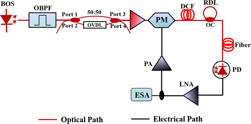
In this Letter, we propose and experimentally demonstrate an OEO based on a single-bandpass MPF and a recirculating delay line (RDL)[23]. The MPF is composed of a BOS, a fiber Mach–Zehnder interferometer (MZI), a phase modulator (PM), a dispersion compensating fiber (DCF), an RDL, and a photodetector (PD). The tunability of the OEO can be implemented by tuning the optical variable delay line (OVDL) to change the length difference between two arms of the MZI. Additionally, the cascade of the RDL in the loop can avoid mode hopping due to the Vernier effect by the combination of the single loop and the RDL. Furthermore, the RDL is actually an infinite impulse response (IIR) filter, which can enhance the Q-factor of the MPF and strengthen the mode selecting ability. The scheme improves the stability of the generated microwave signal[24].
Sign up for Chinese Optics Letters TOC. Get the latest issue of Chinese Optics Letters delivered right to you!Sign up now
Compared with the previous work[22], we only use a single loop in the OEO, avoiding multiple optical-to-electrical conversion and therefore reducing the complexity. The cascade of the MPF and RDL can effectively suppress the side modes. In addition, we discuss and optimize the RDL feedback ratio to realize the MPF with a high out-of-band rejection, which can reduce the out-of-band noise. In our experiment, the frequency tuning range of the OEO is from 10.3 GHz to 26.7 GHz with a 100 MHz step. The single sideband (SSB) phase noise is @10 kHz. Simultaneously, the OEO’s stability measurement validates our theory prediction by Allan variance which shows more than two orders of improvement from the 1 s to 100 s averaging time.
The setup of the proposed OEO is shown in Fig. 1. The output of a BOS is injected to a fiber MZI after being filtered by an optical bandpass filter (OBPF). The fiber MZI is constituted of two optical couplers (OCs) and an OVDL. The splitting ratios of the two couplers are 50:50. The output of the MZI is amplified by an erbium-doped fiber amplifier (EDFA) and then fed to the PM. The phase-modulated signal passes through the DCF, RDL, and standard single mode fiber, and is detected by the PD. The photo-detected electrical signal is amplified and sent to the RF port of the PM to form a closed loop. The cascading of the low phase noise amplifier (LNA) and power amplifier (PA) is utilized to offer a sufficient gain to guarantee the oscillation of the OEO.
The MPF response shown in Fig. 1 is the responses from the finite impulse response (FIR) filter realized by the BOS based MPF and the IIR filter presented by the RDL. As illustrated in Fig. 1, after the fiber MZI, the output electrical field of port 3 is expressed as where is electrical field of the filtered BOS, is the propagation constant of the OVDL, and is the length difference between the upper and lower arms of the MZI. The transfer function of the MZI can be expressed as[15]where is the center frequency of the BOS, is the wavelength spacing of the MZI defined as , is the light velocity in the transmission medium, and is the effective refractive index of the OVDL.
Then the optical power at port 3 is
Concerning only the first-order modulation sidebands, the electrical field of each frequency component through the PM can be expressed as where is the th Bessel function of the first kind, is the modulation index of the PM, and is the angular frequency of RF applied to the PM.
The phase-modulated signal is sent to the wavelength-dependent time delay line. Assuming , the DCF is a phase-only filter and the transfer function is . When is expanded by the Taylor series centered at , the can be written as[15]where , are the dispersion and the length of the DCF, respectively, and is the group delay time at .
The frequency response of the FIR filter (i.e., the MPF without RDL) can be expressed as[20]
According to Eqs. (2)–(6), the transfer function of the MPF formed by the FIR filter can be derived as where is the optical power sent to the OBPF and is the filtering bandwidth of the OBPF. The OBPF is regarded as rectangular-shaped, the spectrum distribution of the amplified spontaneous emission is , and is defined as .
From Eq. (7), neglecting the baseband frequency response term, the MPF is a single-bandpass filter. When , the center frequency of the MPF can be described as where is the time delay difference between two arms of the MZI. The center frequency of the single-bandpass MPF is proportional to , and inversely proportional to the total dispersion amount of the DCF.
Simultaneously, the bandwidth of the MPF can be derived as[21]
The bandwidth of the FIR filter is inversely proportional to the total dispersion amount of the DCF and the bandwidth of the BOS.
Next, we discuss the IIR filter response. The IIR filter is formed by connecting one of the input ports and one of the output ports of a optical coupler. The left two ports act as the input and output ports of the IIR filter. The RF transfer function of the RDL is defined as[23]where is the coupling ratio of the optical coupler, , and is the round trip time delay of the RDL. When , that is , the IIR filter response has the maximum out-of-band rejection. Then Eq. (10) can be simplified as
Finally, the frequency response of the MPF by cascading the FIR and the IIR filters is
The MPF serves as a mode selector in the proposed OEO. The OEO is oscillating when the closed-loop gain is larger than a unit. The power of the generated electrical signal is given by[24]where , , are the phase shifts induced by the DCF, RDL, and amplifiers, respectively.
According to Eqs. (7), (11), (12), and (13), the simulation results are given in Fig. 2. Figure 2(a) shows the simulated FIR response of the singe-bandpass MPF. The 3 dB bandwidth is hundreds of MHz. Figure 2(b) shows the IIR response. The length of the RDL is 2 m and the coupling ratio is 0.33. The spacing of the peaks of the frequency response is 100 MHz. Figure 2(c) is the frequency response of the cascade of FIR and IIR filters. It can be seen that the effective 3 dB bandwidth is getting narrow for the OEO, which is of benefit to the oscillating mode selecting. Moreover, the Vernier effect can be obtained between two modes that are determined by the length of the DCF and RDL, and it can avoid mode hopping and therefore make the OEO more stable. Figure 2(d) is the power spectrum of the generated signal by the OEO. The frequency depends on the center frequency of the MPF.
Figure 2.Simulated frequency response of (a) the FIR filter, (b) the IIR filter, and (c) the cascade of the FIR and IIR filters. (d) The power spectrum of the oscillating signal of the OEO.
By tuning the OVDL, different time delay differences between the two arms of the fiber MZI can be obtained, which leads to the center frequency tuning of the MPF. When the tunable MPF is placed into the OEO as a mode selector, the tuning of the oscillating frequency can be achieved. Figure 3 illustrates the simulated electrical spectra of the OEO from DC to 35 GHz with a 1 GHz step based on Eq. (13). In the simulation, the 1 km DCF has a total dispersion of (), and the center wavelength and the bandwidth of the BOS are 1550 nm and 10 nm, respectively. The amplitude response of the generated RF signal will degrade rapidly when the frequency is lower than 10 GHz or higher than 27 GHz. The decay of the frequency response is induced by the dispersion of the fiber.
Figure 3.Simulated electrical spectra at different frequencies. (solid lines: the electrical spectra of the RF signals; dashed line: the frequency response induced by the chromatic dispersion of the DCF).
An experiment is carried out based on the setup shown in Fig. 1. The BOS is sent to the OBPF with the center wavelength at 1550 nm and the bandwidth of 10 nm. After the OBPF, a rectangular-shaped optical spectrum is obtained by an optical spectrum analyzer (Advantest Q8384), as shown in Fig. 4(a). The OVDL has a 600 ps tuning range in our system.
Figure 4.Optical spectra of the BOS (a) after the OBPF and (b) after the MZI.
After the MZI, an interference optical spectrum is achieved, as shown in Fig. 4(b). The wavelength spacing of the peaks of the optical spectrum is determined by the length difference between the two arms of the MZI. The frequency response of the MPF formed by the cascading of the BOS based MPF and the RDL is measured using a vector network analyzer (VNA, Keysight N5247A), as shown in Fig. 5. The 3 dB bandwidth is about 600 MHz. By adjusting the OVDL, the center frequency can be changed. The center frequency of the tunable single-bandpass MPF is changed from 10.6 GHz to 29.6 GHz with a 1 GHz step.
Figure 5.MPF’s frequency response at different frequency points measured by the VNA.
To verify whether the RDL could improve the OEO’s side mode suppression, the electrical spectra of the OEO with and without the RDL are measured by the spectrum analyzer (Advantest R3182), as shown in Figs. 6(a) and 6(b), respectively. The incorporation of the RDL strongly reduces the side modes and improves the spectral purity of the oscillating signal.
Figure 6.Electrical spectra of the 20 GHz oscillating signal (a) with and (b) without the RDL.
By adjusting the OVDL, we can achieve a tuning range from 10.3 GHz to 26.7 GHz with a coarse step of 1 GHz, as illustrated in Fig. 7(a). Moreover, we also investigate the fine-tuning of the OEO, as shown in Fig. 7(b); the tuning step is 100 MHz, which is determined by the round trip time delay of the RDL. With longer round trip time delays, the tuning step can be further decreased.
Figure 7.Tuning electrical spectra (a) from 10.3 to 26.7 GHz with a step of 1 GHz and (b) from 18.2 to 19.2 GHz with a step of 100 MHz.
The frequency stability of the proposed OEO is also measured, as shown in Fig. 8(a). The measuring time is 500 s. The frequency drifting is about tens of kHz without the RDL. The frequency stability is significantly improved with the insertion of the RDL in the OEO loop. Figure 8(b) shows that the Allan variance at a 1 s average of the OEO with the RDL is two orders lower than that of the OEO without the RDL. The long-term stability is improved. In addition, the influence of the environmental temperature drift on the frequency stability of a fiber-based OEO is expected to be 8 × 10⁻⁶ °C−1[25]. The frequency stability of the OEO can be improved by phase-locking techniques.
Figure 8.(a) Frequency fluctuations and (b) Allan variances of the OEO.
The phase noises of the OEO at different frequency points (10.3 GHz, 15.5 GHz, 20.5 GHz, 25.5 GHz) are measured by a signal source analyzer (Keysight E5052B & E5053A), as shown in Fig. 9(a). All the phase noises are at a 10 kHz offset. The phase noise is independent of the frequency. The phase noise results are kept and without deterioration with the increased frequency. Additionally, the phase noises at a frequency of 10.3 GHz with different fiber lengths are evaluated, as illustrated in Fig. 9(b). The fiber length is changed by cascading a single-mode fiber (SMF) to the DCF. For comparison, two SMFs with lengths of 1 km and 3 km are used to form three OEOs. The three OEOs are formed by a 1 km DCF, a 1 km DCF cascading a 1 km SMF, and a 1 km DCF cascading a 3 km SMF, respectively. The measured results are , , and at an offset of 10 kHz, for the three OEOs, respectively. The longer the fiber used, the lower the phase noise that can be obtained. The side modes spacings are integer multiples of frequency intervals 200 kHz, 100 kHz, and 50 kHz, respectively, which are determined by the total length of the optical fiber loop.
Figure 9.SSB phase noise comparison (a) at different frequency points and (b) with different fiber lengths at 10.3 GHz.
In conclusion, a wideband tunable OEO based on a single-bandpass MPF and an RDL is proposed and experimentally demonstrated. A frequency tuning range from 10.3 to 26.7 GHz is achieved and a 100 MHz-step tunability is also demonstrated from 18.2 to 19.1 GHz. The corresponding phase noise of the generated microwave signal is about @10 kHz for the 10.3 GHz signal. The cascading of the single-bandpass MPF and the RDL strongly suppresses the side modes due to the Vernier effect. The Allan variance at a 1 s average of the OEO with the RDL is two orders lower than that of the OEO without the RDL.
[25] M. Kaba, H.-W. Li, A. S. Daryoush, J.-P. Vilcot, D. Decoster, J. Chazelas, G. Bouwmans, Y. Quiquempois, F. Deborgies. IEEE Microw. Mag., 7, 38(2006).