• Chinese Journal of Lasers
  • Vol. 49, Issue 18, 1803001 (2022)
Yifan Liu1、2, Baosheng Zhou3, Tao Zhang3, Detian Niu3, Shijia Wang2, Jianhui Su1、2, Xiaoguo Song1、2, and Caiwang Tan1、2、*
Author Affiliations
  • 1State Key Laboratory of Advanced Welding and Joining, Harbin Institute of Technology, Harbin 150001, Heilongjiang, China
  • 2Shandong Provincial Key Laboratory of Special Welding Technology, Harbin Institute of Technology at Weihai, Weihai 264209, Shandong, China
  • 3National Invitation Center of High-Speed Train at Qingdao, Qingdao 266108, Shandong, China
  • show less
    DOI: 10.3788/CJL202249.1803001 Cite this Article Set citation alerts
    Yifan Liu, Baosheng Zhou, Tao Zhang, Detian Niu, Shijia Wang, Jianhui Su, Xiaoguo Song, Caiwang Tan. Laser Joining of Carbon Fiber Reinforced Plastics to Titanium Alloy via Laser Texturing[J]. Chinese Journal of Lasers, 2022, 49(18): 1803001 Copy Citation Text show less
    Principle of nanosecond laser texturing and grid pattern of micro-texture
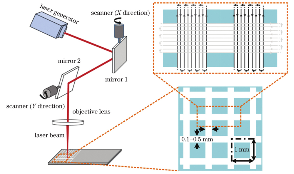
    Fig. 1. Principle of nanosecond laser texturing and grid pattern of micro-texture
    Schematic of laser joining of CFRP to TC4
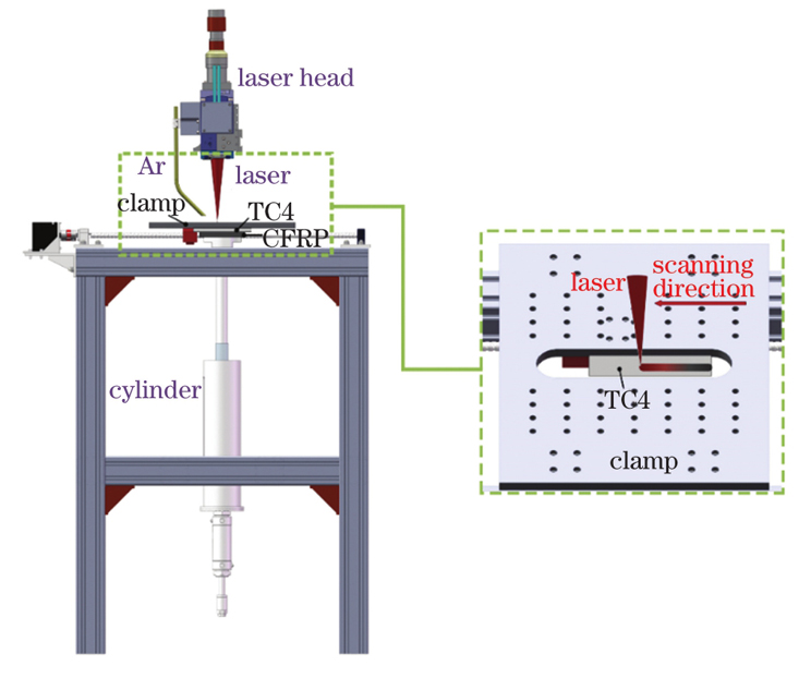
    Fig. 2. Schematic of laser joining of CFRP to TC4
    Schematic of tensile-shear testing on TC4/CFRP laser bonded joint
    Fig. 3. Schematic of tensile-shear testing on TC4/CFRP laser bonded joint
    Three-dimensional morphologies of micro-texture with various widths on TC4 surface. (a) Untreated TC4; (b) micro-texture width of 0.1 mm; (c) micro-texture width of 0.2 mm; (d) micro-texture width of 0.3 mm; (e) micro-texture width of 0.4 mm; (f) micro-texture width of 0.5 mm
    Fig. 4. Three-dimensional morphologies of micro-texture with various widths on TC4 surface. (a) Untreated TC4; (b) micro-texture width of 0.1 mm; (c) micro-texture width of 0.2 mm; (d) micro-texture width of 0.3 mm; (e) micro-texture width of 0.4 mm; (f) micro-texture width of 0.5 mm
    Surface roughness of TC4 with different micro-texture widths
    Fig. 5. Surface roughness of TC4 with different micro-texture widths
    Contact angle of melted CFRP on TC4 surface with various micro-texture widths
    Fig. 6. Contact angle of melted CFRP on TC4 surface with various micro-texture widths
    Macroscopic morphologies of typical laser joined joint of CFRP to TC4. (a) Top view; (b) back view
    Fig. 7. Macroscopic morphologies of typical laser joined joint of CFRP to TC4. (a) Top view; (b) back view
    Optical morphologies of typical laser joined TC4/CFRP joints near interface with various micro-texture widths.(a) Untreated TC4; (b) micro-texture width of 0.1 mm; (c) micro-texture width of 0.2 mm; (d) micro-texture width of 0.3 mm; (e) micro-texture width of 0.4 mm; (f) micro-texture width of 0.5 mm
    Fig. 8. Optical morphologies of typical laser joined TC4/CFRP joints near interface with various micro-texture widths.(a) Untreated TC4; (b) micro-texture width of 0.1 mm; (c) micro-texture width of 0.2 mm; (d) micro-texture width of 0.3 mm; (e) micro-texture width of 0.4 mm; (f) micro-texture width of 0.5 mm
    SEM morphologies and elements distributions of typical laser joined TC4/CFRP joint. (a)(b) Untreated TC4; (c)(d) micro-textured TC4
    Fig. 9. SEM morphologies and elements distributions of typical laser joined TC4/CFRP joint. (a)(b) Untreated TC4; (c)(d) micro-textured TC4
    Fitting curves of Ti2p XPS peaks of TC4/CFRP laser joining interface with laser micro-texture
    Fig. 10. Fitting curves of Ti2p XPS peaks of TC4/CFRP laser joining interface with laser micro-texture
    Shear fore of TC4/CFRP joint with various micro-texture widths
    Fig. 11. Shear fore of TC4/CFRP joint with various micro-texture widths
    Three-dimensional fracture images of typical TC4/CFRP joint
    Fig. 12. Three-dimensional fracture images of typical TC4/CFRP joint
    Scanning electron microscopy (SEM) images and element distributions of typical TC4/CFRP joint fracture
    Fig. 13. Scanning electron microscopy (SEM) images and element distributions of typical TC4/CFRP joint fracture
    Schematic of laser joining mechanism
    Fig. 14. Schematic of laser joining mechanism
    ElementMass fraction /%
    Fe0.3
    Al5.5
    V3.5
    C≤0.1
    TiBalance
    Table 1. Chemical composition of TC4 sheet
    Process parameterValue
    Frequency /kHz200
    Laser power /W70
    Defocus distance /mm0
    Scanning speed /(mm·s-1)300
    Depth of micro-texture /μm110
    Width of micro-texture /mm0.1, 0.2, 0.3, 0.4, 0.5
    Table 2. Parameters employed in laser texturing TC4 sheet surface
    Process parameterValue
    Laser power /W750
    Scanning speed /(m·min-1)0.8
    Laser beam diameter /mm0.95
    Flow rate of argon gas /(L·min-1)20
    Table 3. Parameters of TC4 and CFRP laser joining
    Yifan Liu, Baosheng Zhou, Tao Zhang, Detian Niu, Shijia Wang, Jianhui Su, Xiaoguo Song, Caiwang Tan. Laser Joining of Carbon Fiber Reinforced Plastics to Titanium Alloy via Laser Texturing[J]. Chinese Journal of Lasers, 2022, 49(18): 1803001
    Download Citation