Abstract
We employ quantum state and process tomography with time-bin qubits to benchmark a city-wide metropolitan quantum communication system. Over this network, we implement real-time feedback control systems for stabilizing the phase of the time-bin qubits and obtain a 99.3% quantum process fidelity to the ideal channel, indicating the high quality of the whole quantum communication system. This allows us to implement a field trial of high-performance quantum key distribution using coherent one way protocol with an average quantum bit error rate and visibility of 0.25% and 99.2% during 12 h over 61 km. Our results pave the way for the high-performance quantum network with metropolitan fibers.Quantum internet connects quantum computers with quantum communication channels[1,2], facilitating the transmission of information carried by qubits. Recently, free-space quantum communication has had tremendous advancement[3]. On the other hand, fiber-based quantum communication is a natural candidate for the realization of transmitting quantum information in the metropolitan scale. This is because of its compatibility with an established fiber network for classical communication[4–12].
To obtain the full knowledge of the transmission process over the fiber channel is quintessential for the security and reliability of quantum communication systems. A method for reconstructing the quantum process is known as quantum process tomography (QPT)[13]. Based on the method, we can fully describe the channels and understand the possible errors during transmission[14–16]. A time-bin qubit is a promising quantum information carrier over fiber networks [e.g., intercity quantum teleportation[17,18] and quantum key distribution (QKD)[19–21]] because it is easy to prepare, is polarization independent, and stable in the fiber. However, to the best of our knowledge, there are no tests of QPT in a fiber network based on time-bin qubits encoded in weakly coherent states, let alone in an installed metropolitan telecommunication fiber network[14,15,22–24]. Here, we carry out tomographic protocols based on time-bin encoding to characterize an installed commercial fiber network between the two campuses of Nanjing University. The physical distance between the two campuses is about 30.5 km. We use a fiber loop (about 61 km in total with a loss of 28.02 dB) to guide the photon back to the Gulou Campus at Nanjing University. By doing so, we double the attenuations of the signal, which enables us to characterize our QKD system under various operating conditions and provides important metrics of our system with high-transmission loss. Full reconstruction of the channel helps us better understand the channel conditions. To verify the reliability of the QPT experiment, we then implement a field trial of coherent one way (COW) QKD[20] with continuous and autonomous feedback control over 12 h. We obtain the averaged quantum bit error rates (QBERs) of 0.25% and visibilities of 99.2%, respectively, matching well with the QPT results. Such a technique can be used as a standardized method for the calibration of quantum fiber networks in the future. The COW protocol can be naturally extended to a three-state protocol for considering the coherent attacks, which has been studied both theoretically and experimentally[25–27].
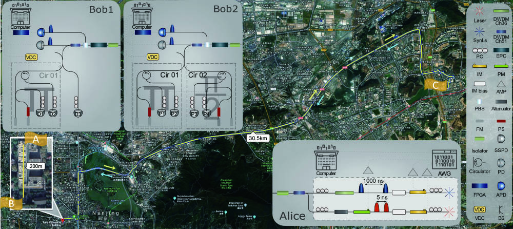
An aerial map of the Nanjing University quantum network, identifying the locations of Alice and Bob, is shown in Fig. 1 with the schematics of the experimental setup as the insets. There are three nodes in the network with two nodes (node A and node B) at the Gulou Campus and one node (node C) at the Xianlin Campus. These nodes are separated by distances of 0.2 km and 30.5 km, respectively; the superconducting nanowire single-photon detector (SSPD) is situated at node B. The sender (Alice, at node C for remote experiment and at node A for looped back field trials) prepares time-bin-encoded weak laser pulses and sends them to the receiver (Bob) at node A over the commercial fibers, considered as a quantum channel here. At Alice’s side, we use a continuous-wave laser at 1536.61 nm (ITU-T channel 51) with an intensity modulator (IM) to generate the time-encoded pulses. The pulse width is about 1.5 ns, and the pulse separation is about 5 ns. Then, light is sent through an IM bias controller to lock the operating point of the IM and ensure a stable operation over time and environmental conditions. The subsequent phase modulator (PM) applies a relative phase between two pulses. The attenuator is introduced to reduce the average photon number per pulse. The system is synchronized via co-propagating multiplexed pulses at different wavelength (1548.51 nm, ITU-T channel 36) and polarization with respect to the quantum signals at a rate of 1 MHz. At Alice’s side, the arbitrary wave generator (AWG) is used to drive the PM for the quantum signal and IMs for quantum and synchronization signals, respectively. At Bob’s side, a dense wavelength division multiplexer (DWDM) filter is used to separate the classical and quantum signals. The polarization beam splitter (PBS) and electrical polarization controller (EPC) are used to perform polarization stabilization. For QPT, Bob projects the incoming photon onto the standard Pauli bases at setup Bob2, which is realized by two Faraday–Michelson interferometers (FMIs) with a 1 m difference in the two arms[21], where a phase shifter (PS) is employed to determine the relative phase information of the two time bins. For COW QKD, Bob can decode the qubits at setup Bob1 with a 90:10 beam splitter to passively route most of the photons for arrival time measurements. The remaining 10% are fed into an FMI for measuring the phase coherence. Photons are then transmitted to node B and detected by SSPDs with 80% detection efficiency; the corresponding electronic signals return to node A through coaxial cables and are collected by a field programmable gate array (FPGA) with 156 ps resolution. Note that the three-state protocol can also be implemented in this setup[26]. To optimize the visibility, we develop a real-time proportional-integral-derivative (PID) feedback system, where a thermal PS is used to compensate the phase drifts of the interferometer per 0.47 s with the error count rate in the monitor line as the feedback. The mean photon number of 0.29 per pulse is optimized by considering the measured transmission loss and the detection efficiency according to the security proof by Branciard et al.[28].
Sign up for Chinese Optics Letters TOC. Get the latest issue of Chinese Optics Letters delivered right to you!Sign up now

Figure 1.Schematics of the experimental setup in the Nanjing University optical fiber network. Node A and node B are located in the Zhongying Tang Building and the Electron Microscope Building, respectively, in the Gulou Campus. Node C is located in the Fundamental Laboratory Building in the Xianlin Campus. These nodes are separated by distances of 0.2 km and 30.5 km. Fiber is installed along the yellow line. Abbreviations of components: IM, intensity modulator; IM bias, intensity modulator bias; AMP, amplifier; PM, phase modulator; PBS, polarization beam splitter; BS, beam splitter; PC, polarization controller; EPC, electrical polarization controller; DWDM, dense wavelength division multiplexer; SynLs, synchronized laser; FM, Faraday rotation mirror; PS, phase shifter; SSPD, superconducting single-photon detector; PD, power detector; APD, avalanche photodiode FPGA; field programmable gate array; VDC, variable direct current. Imagery©2020 Google. Map data from Google, Maxar Techonologies, CNES/Airbus.
To characterize the performance of the quantum system, we perform single-qubit quantum-state tomography (QST) on the quantum states transmitted over the 61.1 km looped back fiber. We create photons in, and project them onto, well-defined time-bin states, such as , , , and , where () stands for the quantum state of the photon being an early (late) temporal mode. The density matrices of the six final output states reconstructed by QST are shown in Fig. 2(a) in the green bars, which are very close to the ideal states (black line).
Figure 2.Characterization of the quantum channel. (a) Density matrices of output time-bin-encoded states. (b) State fidelities of the six output states to the ideal states. (c), (d) Real and imaginary parts of the process matrices for the quantum channel with a fidelity of . (e) Bloch sphere representation of the process. The plot shows how the ideal states on the surface of the Bloch sphere (meshed) are influenced by the quantum channel, with the output states lying on the solid surface. The uncertainties in state fidelities are calculated using a Monte Carlo routine assuming Poissonian error.
Figure 2(b) shows the state fidelities, which are defined as the overlap between the ideal states and the final output states. The fidelities for the six states are estimated to be , , , , , and , respectively. The process of transmitting qubits over this quantum channel is quantified by QPT. We choose , , , and as the input states and their corresponding output states to determine the process matrix . The output states are related to the input states through the process density matrix, i.e., , where are the Pauli matrices with being the identity operator. The real and imaginary parts of are shown in Figs. 2(c) and 2(d). The process fidelity is defined as , where is the ideal process matrix. There are three fidelities: the fidelity of the output state to the ideal state (), the fidelity of the input state to the ideal state (), and the fidelity of the output state to the input state (). In our work, we obtain the following: , , and . All the three numbers agree with each other in the statistics. The , , and components of the matrix represent the probabilities of a bit-flip or phase-flip error in the channel. A single-qubit quantum process can be represented graphically when subjected to the quantum process[16]. In Fig. 2(e), we plot the ideal states as a wire grid of the Bloch sphere. After the long-fiber transmission from Alice and Bob, the received quantum states are, although very close to, not the same as the original states. Therefore, the ideal Bloch sphere is deformed into a slightly anisotropic ellipsoid, as shown in the solid blue color.
Having established this high-quality quantum system, we proceed to perform QKD by employing the COW protocol[20,28–34]. The coherent pulses chopped by Alice are either empty or have a mean photon number . Each logical bit of information is defined by the position of a non-empty pulse in neighboring bins, for example, -0 for a logical “0” or 0- for a logical “1”. Decoy sequences - are sent to prevent photon-number-splitting attacks[28]. To obtain the key, Bob measures the arrival time of the photons on his data line, detectors in Bob1 of Fig. 1. In order to avoid Raman noise generated by synchronized signals, along with them we send empty sequences that are not used for coding. Attenuated laser pulses with 1.5 ns width are modulated to signal, decoy, and empty sequences, respectively. Among them, we send decoy sequences with a probability of 7%, which are sufficient to calibrate the phase drifts during the PID feedback time, as well as to detect the presence of an eavesdropper. In order to avoid Raman noise generated by synchronized signals, along with them we send empty sequences with a probability of 3%, which are not used for coding. The remaining 90% of the sequences are encoded as signals to obtain a high key rate. To ensure the security, Bob randomly measures the coherence between successive non-empty pulses, such as bit sequences “1-0” or decoy sequences, with the unbalanced interferometer and detectors D1 and D2. Ideally, due to the coherence between pulses, we have all detections on D1 and no detection on D2. A loss of coherence, hence, reduced visibility, indicates the presence of disturbance, in which case the key is simply discarded. Coherence can be quantified by the visibility of the interference: where and are, respectively, the detector counts of D1 and D2. It is crucial to investigate the system stability under different operating conditions, such as temperature and time. We summarize this information in Table 1, which includes the length of fibers, the date, the measurement time, and the corresponding environment temperature.
| Fiber Links | Length (km) | Total Attenuation (dB) | Date (2019) | Time | Temperature |
|---|
| A-B | 0.2 | 12.95 | 10 pm, Jun. 09 to 10 am, Jun. 10 | 12 h | 22–31°C |
| B-C | 30.5 |
Table 1. Characteristics of Our System under Test
Figure 3 shows the QBER and the interference visibility over a 61.1 km looped back field trial for 12 h. The averaged QBER and visibility of the system are and , respectively, indicating the high performance of our system. These results match state fidelities well, which proves the reliability and accuracy of our QPT method. The figure also illustrates the system’s long-time continuous operation capability. Moreover, from the interference visibility, a phase error rate of about 0.004 can be expected during the key exchange scenario, which is low even compared with other indoor QKD protocols at similar attenuations[34–37].
Figure 3.A 12 h continuous operation of the Nanjing quantum network with excellent system parameters: quantum bit error rate (blue, left vertical axis) and (red, right vertical axis) for COW protocol.
Figure 4 shows the secure key rate (SKR) per pulse as a function of channel attenuation. The error correction efficiency is set to 1.16. The SKRs of 30.5 km (, about 115.6 kbits/s, for 12.95 dB loss) and 61.1 km (, about 3.64 kbits/s, for 28.02 dB loss), marked as red and green pentagrams, respectively, are estimated using the above system parameters with the measured QBER and visibilities. According to the security proof by Branciard et al.[28], it has been shown to be an upper bound under the assumption of collective attacks (i.e., Eve interacts with each individual state using the same strategy). We calculate the key rate in the infinite key scenario. As the channel attenuation increases, the number of counts decreases, and the dark count rates (DCRs) of the SSPDs (about ) become a major component of QBER; thus, the SKR decreases exponentially. With the high visibility and negligible DCRs, our system can tolerate more channel loss, which means a wider area network.
Figure 4.Field trial SKR as a function of attenuation. Green and red pentagrams are our SKR on the network.
With these field tests of our network for quantum communications, we have fully evaluated the quality of the system via both quantum state and process tomography techniques. The QPT technique can be a standardized method for calibrating the quantum fiber networks in the future. We have extended a high security key rate per pulse for the COW protocol over the installed commercial fiber network with a real-time feedback control. Our results pave the way for the high-performance quantum network with metropolitan fibers.
References
[1] H. J. Kimble. Nature, 453, 1023(2008).
[2] S. Wehner, D. Elkouss, R. Hanson. Science, 362, eaam9288(2018).
[3] S. Liao, W. Cai, W. Liu, L. Zhang, Y. Li, J. Ren, J. Yin, Q. Shen, Y. Cao, Z. Li, F. Li, X. Chen, L. Sun, J. Jia, J. Wu, X. Jiang, J. Wang, Y. Huang, Q. Wang, Y. Zhou, L. Deng, T. Xi, L. Ma, T. Hu, Q. Zhang, Y. Chen, N. Liu, X. Wang, Z. Zhu, C. Lu, R. Shu, C. Peng, J. Wang, J. Pan. Nature, 549, 43(2017).
[4] J. Qiu. Nature, 508, 441(2014).
[5] D. Stucki, M. Legre, F. Buntschu, B. Clausen, N. Felber, N. Gisin, L. Henzen, P. Junod, G. Litzistorf, P. Monbaron, L. Monat, J. Page, D. Perroud, G. Ribordy, A. Rochas, S. Robyr, J. Tavares, R. Thew, P. Trinkler, S. Ventura, R. Voirol, N. Walenta, H. Zbinden. New J. Phys., 13, 123001(2011).
[6] M. Sasaki, M. Fujiwara, H. Ishizuka, W. Klaus, K. Wakui, M. Takeoka, S. Miki, T. Yamashita, Z. Wang, A. Tanaka, K. Yoshino, Y. Nambu, S. Takahashi, A. Tajima, A. Tomita, T. Domeki, T. Hasegawa, Y. Sakai, H. Kobayashi, T. Asai, K. Shimizu, T. Tokura, T. Tsurumaru, M. Matsui, T. Honjo, K. Tamaki, H. Takesue, Y. Tokura, J. F. Dynes, A. R. Dixon, A. W. Sharpe, Z. L. Yuan, A. J. Shields, S. Uchikoga, M. Legré, S. Robyr, P. Trinkler, L. Monat, J. Page, G. Ribordy, A. Poppe, A. Allacher, O. Maurhart, T. Länger, M. Peev, A. Zeilinger. Opt. Express, 19, 10387(2011).
[7] M. Peev, C. Pacher, R. Alléaume, C. Barreiro, J. Bouda, W. Boxleitner, T. Debuisschert, E. Diamanti, M. Dianati, J. F. Dynes, S. Fasel, S. Fossier, M. Fürst, J. Gautier, O. Gay, N. Gisin, P. Grangier, A. Happe, Y. Hasani, M. Hentschel, H. Hübel, G. Humer, T. Länger, M. Legré, R. Lieger, J. Lodewyck, T. Lorünser, N. Lütkenhaus, A. Marhold, T. Matyus, O. Maurhart, L. Monat, S. Nauerth, J. Page, A. Poppe, E. Querasser, G. Ribordy, S. Robyr, L. Salvail, A. W. Sharpe, A. J. Shields, D. Stucki, M. Suda, C. Tamas, T. Themel, R. T. Thew, Y. Thoma, A. Treiber, P. Trinkler, R. Tualle-Brouri, F. Vannel, N. Walenta, H. Weier, H. Weinfurter, I. Wimberger, Z. L. Yuan, H. Zbinden, A. Zeilinger. New J. Phys., 11, 075001(2009).
[8] C. Elliott. New J. Phys., 4, 46(2002).
[9] Y. Mao, B. Wang, C. Zhao, G. Wang, R. Wang, H. Wang, F. Zhou, J. Nie, Q. Chen, Y. Zhao, Q. Zhang, J. Zhang, T. Chen, J. Pan. Opt. Express, 26, 6010(2018).
[10] B. Fröhlich, J. F. Dynes, M. Lucamarini, A. W. Sharpe, Z. Yuan, A. J. Shields. Nature, 501, 69(2013).
[11] W. Chen, Z. Han, T. Zhang, H. Wen, Z. Yin, F. Xu, Q. Wu, Y. Liu, Y. Zhang, X. Mo, Y. Gui, G. Wei, G. Guo. IEEE Photon. Technol. Lett., 21, 575(2009).
[12] X. Wang, S. Li, X. Jiang, J. Hu, M. Xue, S. Xu, S. Pan. Chin. Opt. Lett., 17, 060601(2019).
[13] M. A. Nielsen, I. L. Chuang. Quantum Computation and Quantum Information(2010).
[14] F. Bouchard, F. Hufnagel, D. Koutný, A. Abbas, A. Sit, K. Heshami, R. Fickler, E. Karimi. Quantum, 3, 138(2019).
[15] B. Ndagano, B. Perez-Garcia, F. S. Roux, M. McLaren, C. Rosales-Guzman, Y. Zhang, O. Mouane, R. I. Hernandez-Aranda, T. Konrad, A. Forbes. Nat. Phys., 13, 397(2017).
[16] N. Gisin, G. Ribordy, W. Tittel, H. Zbinden. Rev. Mod. Phys, 74, 145(2002).
[17] R. Valivarthi, M. L. G. Puigibert, Q. Zhou, G. H. Aguilar, V. B. Verma, F. Marsili, M. D. Shaw, S. W. Nam, D. Oblak, W. Tittel. Nat. Photon., 10, 676(2016).
[18] Q. Sun, Y. Mao, S. Chen, W. Zhang, Y. Jiang, Y. Zhang, W. Zhang, S. Miki, T. Yamashita, H. Terai, X. Jiang, T. Chen, L. You, X. Chen, Z. Wang, J. Fan, Q. Zhang, J. Pan. Nat. Photon., 10, 671(2016).
[19] A. Boaron, G. Boso, D. Rusca, C. Vulliez, C. Autebert, M. Caloz, M. Perrenoud, G. Gras, F. Bussières, M. Li, D. Nolan, A. Martin, H. Zbinden. Phys. Rev. Lett., 121, 190502(2018).
[20] D. Stucki, N. Brunner, N. Gisin, V. Scarani, H. Zbinden. Appl. Phys. Lett., 87, 194108(2005).
[21] X. Song, H. Li, C. Zhang, D. Wang, S. Wang, Z. Yin, W. Chen, Z. Han. Chin. Opt. Lett., 13, 012701(2015).
[22] W. Liang, S. Wang, H. Li, Z. Yin, W. Chen, Y. Yao, J. Huang, G. Guo, Z. Han. Sci. Rep., 4, 3617(2014).
[23] H. Takesue, Y. Noguchi. Opt. Express, 17, 10976(2009).
[24] D. Bruß. Phys. Rev. Lett., 81, 3018(1998).
[25] D. Rusca, A. Boaron, F. Grünefelder, A. Martin, H. Zbinden. Appl. Phys. Lett., 112, 171104(2018).
[26] D. Bacco, I. Vagniluca, B. Da Lio, N. Biagi, A. Della Frera, D. Calonico, C. Toninelli, F. S. Cataliotti, M. Bellini, L. K. Oxenløwe, A. Zavatta. EPJ Quantum Technol., 6, 5(2019).
[27] D. Bacco, B. Da Lio, D. Cozzolino, F. Da Ros, X. Guo, Y. Ding, Y. Sasaki, K. Aikawa, S. Miki, H. Terai, T. Yamashita, J. S. Neergaard-Nielsen, M. Galili, K. Rottwitt, U. L. Andersen, T. Morioka, L. K. Oxenløwe. Commun. Phys., 2, 140(2019).
[28] C. Branciard, N. Gisin, V. Scarani. New J. Phys., 10, 013031(2008).
[29] X. Tang, A. Wonfor, R. Kumar, R. V. Penty, I. H. White. J. Lightwave Technol., 36, 5230(2018).
[30] P. Sibson, C. Erven, M. Godfrey, S. Miki, T. Yamashita, M. Fujiwara, M. Sasaki, H. Terai, M. G. Tanner, C. M. Natarajan, R. H. Hadfield, J. L. O’Brien, M. G. Thompson. Nat. Commun., 8, 13984(2017).
[31] B. Korzh, C. C. W. Lim, R. Houlmann, N. Gisin, M. J. Li, D. Nolan, B. Sanguinetti, R. Thew, H. Zbinden. Nat. Photon., 9, 163(2015).
[32] D. Stucki, N. Walenta, F. Vannel, R. T. Thew, N. Gisin, H. Zbinden, S. Gray, C. Towery, S. Ten. New J. Phys., 11, 075003(2009).
[33] D. Stucki, C. Barreiro, S. Fasel, J. Gautier, O. Gay, N. Gisin, R. Thew, Y. Thoma, P. Trinkler, F. Vannel, H. Zbinden. Opt. Express, 17, 13326(2009).
[34] G. L. Roberts, M. Lucamarini, J. F. Dynes, S. J. Savory, Z. Yuan, A. J. Shields. Laser Photon. Rev., 11, 1700067(2017).
[35] A. V. Gleim, V. I. Egorov, Y. V. Nazarov, S. V. Smirnov, V. V. Chistyakov, O. I. Bannik, A. A. Anisimov, S. M. Kynev, A. E. Ivanova, R. J. Collins, S. A. Kozlov, G. S. Buller. Opt. Express, 24, 2619(2016).
[36] B. Korzh, N. Walenta, R. Houlmann, H. Zbinden. Opt. Express, 21, 19579(2013).
[37] Z. Yin, Z. Han, W. Chen, F. Xu, Q. Wu, G. Guo. Chin. Phys. Lett., 25, 3547(2008).