
Chen ZHANG, Wei WANG, Tao SONG, Jie HUANG, Yi-Chao CAO, Di-Wei LIU, Min HU, Kai-Chun ZHANG, Zhen-Hua WU, [in Chinese], Ren-Bin ZHONG, Tao ZHAO, Seng GONG, Sheng-Gang LIU. Detailed investigations on double confocal waveguide for a gyro-TWT[J]. Journal of Infrared and Millimeter Waves, 2020, 39(5): 547
- Journal of Infrared and Millimeter Waves
- Vol. 39, Issue 5, 547 (2020)
Abstract
Introduction
High average-power gyrotron traveling-wave tubes (gyro-TWT) have abroad applications in modern communication and radar systems[
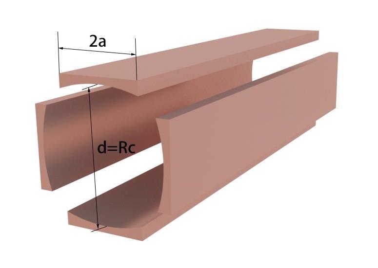
The drawback of the gyro-TWT with a single confocal structure is the relatively low beam-wave interaction efficiency because the conventional annular electron beam is located in the region with different strength of the coupling to the operating mode. One of the possible solutions for mitigating this drawback is to use a double confocal structure. A double confocal waveguide consists of two identical but perpendicular single confocal waveguides in x and y direction, respectively, as shown in Fig.1. The transverse field distribution in a double confocal waveguide is more uniform than that in a single confocal waveguide, so the conventional thin annular electron beam can interact more efficiently with the RF field in a double confocal waveguide. The theoretical analysis and PIC simulation confirmed that the beam-wave interaction efficiency increases obviously in a double confocal waveguide [
![]()
Figure 1.3-D configuration of a double confocal waveguide
In order to utilize a double confocal waveguide as a beam-wave interaction structure in a gyro-TWT, it is necessary to make clear the eigenmodes and their corresponding electromagnetic (EM) characteristics in a double confocal waveguide. In this paper, the EM characteristics of a double confocal waveguide for a gyro-TWT will be investigated in details. The rest of this paper is organized as following. The investigation on eigenmodes in a double confocal waveguide is presented in section 1, in section 2, the diffraction loss is discussed. Summary and conclusion are presented in section 3.
1 Eigenmodes of a Double Confocal Waveguide
The double confocal waveguide is an open structure formed by four identical symmetrically placed curved cylindrical mirrors, in which four mirrors with a radius of Rc and a mirror width of 2a are separated with a distance of d. EM wave is reflected among mirrors. There are two kinds of stable modes with different reflection paths in a double confocal waveguide. The first steady-state mode, namely, the superposition mode, is superposed by two perpendicular in-phase or anti-phase field, as shown in Fig. 2(a). The second steady-state mode, namely, the ring mode, is formed by the consecutive reflection of the field among four mirrors in clockwise or counterclockwise directions, as shown in Fig. 2(b).
![]()
Figure 2.The diagram of the modes in a double confocal waveguide (a) Superposition mode; (b) Ring mode
All resonator dimensions are assumed large compared to a wavelength; the eigenmodes of the resonator are therefore obtainable from a self-consistent field analysis using Huygens’ Principle. The Fresnel field Up at the point of observation is given by the surface integral [
where k is the propagation constant, ρ is the distance from a source point on the mirror to the point of observation and θ is the angle between ρ and the normal of the source point.
1.1 Superposition modes
For a superposition mode, which is superposed by two perpendicular standing wave in x and y direction, respectively, and the eigensolution of the standing wave is as follows. In Fig.3, the field U2(x2) on mirror S2 can be obtained in term of an integral of the known field U1(x1) on mirror S1 in y direction with eq. (1).
![]()
Figure 3.Confocal waveguide with spherical reflectors
The eigenfunctions of the modes in a confocal waveguide can be obtained by making sure that the field distribution over S1 canreproduce itself with a constant over S2, namely, U2(x2) = bmU1(x1), where bm is general complex, including both the amplitude and phase changes. In this case, eq. (2) can be rewritten as following
with
For this general solution, the eigenvalues can be expressed as. The amplitude of bm is related to the diffraction loss, and the phase of bm determines the phase shift of the mode from S1 to S2, where kd is the geometric phase shift and is the additional phase shift. The phase shift of a complete field reflection in the cross section of the resonator must be an integer n times of 2π, namely. . By solving eq. (3), the cut-off wavenumber of the superposition mode can be written as
The field between S1 and S2 can be calculated based on Huygens’ Principle as presented in eq. (1). Approximately, the field distribution between S1 and S2 can be considered as a superposition of two Gaussian beams. The membrane function of standing wave (superposition of two Gaussian beams) can be written as [
, (6)
where
here, Hm(τ) is the Hermite polynomial and .
Similarly, the field distribution between two mirrors in x direction can be calculated in the same way. The superposition mode can be considered as a liner superposition of two in-phase or anti-phase standing waves, and the membrane function can be expressed as following:
where has been expressed in eq.(6). With the membrane functions and of the superposition modes in a double confocal waveguide, by solving the Maxwell’s equations in a Cartesian coordinate system, the field components of TEmn mode can be obtained.
The magnitude of the transverse electric field of the superposition mode in a double confocal waveguide is presented in Fig. 4. Fig. 4 (a), (b), (c) and (d) are the field of the superposition ,,and modes simulated by commercial CST software, the theoretical results of the field are presented in Fig.4 (e), (f), (g) and (h). The theoretical results agree well with those obtained by the commercial CST software. It is worth noting that the theoretical calculation only includes the central area surrounded by the mirror, and the diffraction field between the mirrors is not included in the theoretical calculation.
![]()
Figure 4.The magnitude of electric field of the superposition modes in a double confocal waveguide (a), (b), (c) and (d) are the results simulated by commercial CST software; (e), (f), (g) and (h) are the theoretical results.
In the Cartesian coordinate system, the coupling factor (Form factor) characterizing the Lorentz force on electrons can be expressed as[
Fig. 5 presents the normalized beam-wave coupling factor of the double confocal mode and the single confocal modeTE06 versus the guiding center radius Rb, and the beam-wave coupling factor in a double confocal waveguide is greater than that in a single confocal waveguide.
![]()
Figure 5.Normalized beam-wave coupling coefficient versus
1.2 Ring modes
The other kind of mode in a double confocal waveguide is the ring mode. The ring mode is formed by the consecutive reflection among four mirrors in clockwise or counterclockwise directions.
![]()
Figure 6.Coordinate systems for the ring mode
Based on the scalar formulation of Huygens’ Principle in eq. (1), if we know the field distribution U1 (y1) on mirror M1, we can calculate the field U2 (y2) on mirror M2. Then, the field U2 (y2) is reflected to M3 in the same way to form U3 (y3). It is conceivable that after multiple reflections the field will eventually reach a steady state. U3 (y3) and U1 (y1) satisfy the following relationship: U3(y2) = bmU1(y1). The resulting integral equation is presented as follows
In eq. (13), Kmn are defined as
where ρmnrepresents the distance between any two points on mirror Mm and mirror Mn [
For this general solution, the eigenvalues can be expressed as. By solving eq. (13), the cutoff wavenumber of the ring mode TE0n can be written as
where n is an integer for the mode index which represents the number of maxima from M1 to M3.The electric field at arbitrary point between M1 and M2 can be obtained by calculating the integral of eq.(1) with U1(y1) presented in eq.(13).
The field distribution between two adjacent mirrors also can be considered as a standing-wave field formed by the superposition of Gaussian beams propagating clockwise and counterclockwise. The expression of the membrane function of the ring mode can be written as:
where has been expressed in (6).
The transverse field distribution of the ring modes is shown in Fig. 7. Fig. 7 (a) and (b) is the simulation result of the field distribution from CST, Fig. 7 (c) and (d) is the theoretical calculation result. The theoretical results agree well with those obtained by the commercial CST software.
![]()
Figure 7.The magnitude of the electric field of the ring mode,(a) and (b) are the results from the commercial CST software; (c) and (d) are the theoretical results.
1.3 Mode density
Table I gives the cutoff frequency of the modes whose cutoff frequency is around 263GHz in a double confocal waveguide with Rc=3.6mm and a=1.2mm. Clearly, the cutoff frequencies of the superposition mode and the ring mode calculated by eqs. (5) and (16) agree well with the simulation results from CST.
| Mode | Theoretical | Simulation |
|---|---|---|
| TE09 (ring mode) | 279.2 GHz | 277.8 GHz |
| TE06 (superposition mode) | 260.4 GHz | 260.1GHz |
TE08 (ring mode) TE15 (superposition mode) | 249.8 GHz 239.6 GHz | 249.5GHz 237.2 GHz |
Table 1. Cut-off frequency of Eigenmodes
The mode densities in a double confocal waveguide, in a single confocal waveguide and in a cylindrical waveguide are presented in Fig. 8, it is obvious that the mode density in a double confocal waveguide is higher than that in a single confocal waveguide, but less than that in a cylindrical waveguide. This is because there are more stable paths for the modes in a double confocal waveguide than in a single confocal waveguide. In addition, the in-phase superposition mode and the anti-phase superposition mode are the degenerate mode, so only one curve is used to represent these two modes in Figure 8(c).
![]()
Figure 8.Dispersion curve.(a) Dispersion curve in a cylindrical waveguide. (b) Dispersion curve in a single confocal waveguide. (c) Dispersion curve in a double confocal waveguide.
2 Diffraction losses
For a double confocal waveguide, it is possible to diffract part of power out of the waveguide by means of the gaps among the mirrors; it is helpful against the parasitic oscillation in a gyro-TWT. Table II gives the diffractive loss of different modes in a double confocal waveguide with Rc=3.6mm and a=1.2mm. It is found that the diffractive loss of the anti-phase superposition mode TE06 mode is far less than that of the potential parasitic modes.
| Mode | Total Loss (dB/cm) | Interaction |
|---|---|---|
| TE09 (ring mode) | 28.2dB | Forward |
| TE06 (in-phase superposition mode) | 17.8 | Forward |
| TE06 (anti-phase superposition mode) | 2.03 | Forward |
| TE08 (ring mode) | 13.9 | BWO |
| TE15 (in-phase superposition mode) | 4.8 | BWO |
| TE15(anti-phase superposition mode) | 30.1 | BWO |
Table 2. Total loss
Fig. 9 shows the effect of the gap size on the diffraction losses of the anti-phase superposition mode TE06 mode, which is expected to be the operating mode of the Gyro-TWT.
![]()
Figure 9.Variation of diffraction losses of the anti-phase superposition mode TE06 mode with the aperture size.
3 Conclusion
The electromagnetic characteristics of the double confocal waveguide for a gyro-TWT is investigated in details. There are two kinds of steady-state modes in a double confocal waveguide, namely, the superposition mode and the ring mode. The superposition mode includes in-phase and anti-phase superposition mode. With the scalar formulation of Huygens’ Principle, the eigenvalue and the field distribution of these two kinds of modes have been calculated, and the theoretical calculation results agree well with those from the commercial CST software. Meanwhile, the diffractive loss has also been calculated with CST software. If the anti-phase superposition mode TE06 mode is chosen as an operating mode in a gyro-TWT, the diffractive loss of the potential parasitic modes, such as the ring mode TE08 and TE09 modes, the superposition mode TE06 (in-phase) TE15 (in-phase and anti-phase) modes is far greater than that of the operating mode. It means that the potential parasitic modes can be suppressed effectively by means of its own diffractive loss in a double confocal waveguide. The mode density in a double confocal waveguide is higher than that in a single confocal waveguide, but far lower than that in a cylindrical waveguide. Compared to the single confocal waveguide, a higher beam-wave interaction efficiency can be obtained in a double confocal waveguide for a gyro-TWT, it is an appropriate choice to choose a double confocal waveguide as the beam-wave interaction structure in a gyro-TWT.
References
[1] K R Chu. Overview of research on the gyrotron traveling-wave amplifier. Plasma ence IEEE Transactions on, 30, 903-908(2002).
[2] G S Nusinovich, H Li. Theory of gyro-travelling-wave tubes at cyclotron harmonics. International Journal of Electronics, 72, 895-907(1992).
[3] K R Chu, H Y Chen, C L Hung et al. Ultrahigh Gain Gyrotron Traveling Wave Amplifier. Physical Review Letters, 81, 4760-4763(1998).
[4] J R Sirigiri, M A Shapiro, R J Temkin. High-Power 140-GHz Quasioptical Gyrotron Traveling-Wave Amplifier. Physical Review Letters, 90, 258302(2003).
[5] A V Soane, M A Shapiro, S Jawla et al. Operation of a 140-GHz Gyro-Amplifier Using a Dielectric-Loaded, Severless Confocal Waveguide. IEEE Transactions on Plasma ence IEEE Nuclear & Plasma ences Society, 45, 2835(2017).
[6] W Hu, M A Shapiro. 140-GHz gyrotron experiments based on a confocal cavity. IEEE Transactions on Plasma ence, 26, 366-374(1998).
[7] W Fu, X Guan, Y Yan. Harmonic terahertz gyrotron with a double confocal quasi-optical cavity. Physics of Plasmas, 26(2019).
[8] G S Nusinovich. Efficiency of the gyrotron with single and double confocal resonators. Physics of Plasmas, 25, 073104(2018).
[9] , K Wilh. Interference spectroscopy. Part I: Erratum. Journal of the Optical Society of America (, 32, 185-0(19171983).
[10] G D Boyd, H Kogelnik. Generalized confocal resonator theory. Bell Labs Technical Journal, 41, 1347-1369(1962).
[11] G D Boyd, J P Gordon. Confocal multimode resonator for millimeter through optical wavelength masers. Bell Labs Technical Journal, 40, 489-508(1961).
[12] P O Clark. Self‐Consistent Field Analysis of Multireflector Optical Resonators. Journal of Applied Physics(1965).

Set citation alerts for the article
Please enter your email address
© Copyright 2018-2021 | Chinese Laser Press. All Rights Reserved 沪ICP备15018463号-20