1Institute of Modern Optics, Nankai University, Tianjin Key Laboratory of Micro-scale Optical Information Science and Technology, Tianjin 300350, China
2Tianjin Key Laboratory of Optoelectronic Sensor and Sensing Network Technology, Tianjin 300350, China
Active terahertz (THz) beam manipulation is urgently needed for applications in wireless communication, radar detection, and remote sensing. In this work, we demonstrate a liquid crystal (LC) integrated Pancharatnam–Berry (PB) metadevice for active THz beam manipulation. Through theoretical analysis and simulation design, the geometric phase of the PB metasurface is engineered to match the tunable anisotropic phase shift of LCs under an external magnetic field, and dynamic beam deflection accompanied by spin conversion is obtained. The experimental results show that the device realizes a dynamic modulation depth of and maximum efficiency of over 50% for the different spin states. Moreover, due to the broadband operating characteristics of devices at 0.7–1.3 THz, the deflection angles are frequency dependent with a scanning range of over to . Moreover, the two conjugate spin states are always spatially separated in different deflection directions with an isolation degree of over 10 dB. Therefore, this metadevice provides a scheme of active THz beam deflection and spin state conversion, and it also achieves both controllable wavelength division multiplexing and spin division multiplexing, which have important potential in large-capacity THz wireless communication.
1. INTRODUCTION
Terahertz (THz, ) is an electromagnetic frequency range of 0.1–10 THz between microwave and infrared bands, and has important applications in broadband wireless communication, radar monitoring, and remote sensing imaging [1–3]. To carry more information and achieve more accurate feature recognition, the devices for active THz beam deflection and scanning [4,5] are highly desired with a wide range of deflection angles, broad operating frequency bands, and even multi-polarizations. Compared with linearly polarized (LP) waves, left circularly polarized (LCP) and right circularly polarized (RCP) waves with opposite photonic spin angular momentum have unique advantages in target recognition, polarization imaging, chiral material detection, etc [6,7]. Therefore, it is critical to actively manipulate the THz spin beam comprehensively in the spatial domain, spectral domain, and polarization state.
Pancharatnam–Berry (PB) metasurfaces [8–12] consist of geometric phase optical elements that are the function of half-wave plates (HWPs) with spatially varying axes, exhibiting intriguing properties in manipulating photonic spin states with frequency-irrelevant spatial geometric phase distribution. PB metasurfaces have been proposed for many functional devices such as anomalous deflection, generation of special beams, superlenses, and holograms [13–16]. Despite these impressive advances, most of these devices are passive; once the structure is fixed, it can achieve only specific functions in a limited or even narrow frequency band, which hinders the practical applications of PB metasurfaces. The most efficient way to overcome this problem is to integrate functional materials into the structural design of metasurfaces, including semiconductor materials, phase change materials, liquid crystals (LCs), etc. [17–22]. For example, Li et al. [21] developed an all-optical THz PB metasurface that can effectively manipulate THz beams but works only at the single frequency of 1.09 THz, and the efficiency is still low. Kim et al. [22] proposed a gate-controlled THz PB metasurface that combined graphene to modulate the intensity of anomalous refracted waves. Although active tuning was achieved, the modulation depth was limited to 28%.
LC material is a mature scheme in the visible and near-infrared regimes for spatial phase modulation, polarization control, and active optical devices due to its tunable optical anisotropy, which can be actively controlled by external fields including thermal, optical, electric, and magnetic fields [23,24]. LCs also provide new opportunities for dynamic manipulation of the THz wave. Recently, various active THz devices have been reported based on LC materials, such as tunable absorbers, modulators, phase shifters, and wave plates [25–28]. In general, beam scanning can be achieved by independently manipulating LC phase cells [29], for example, Wu et al. [30] achieved multi-beam scanning with a deflection efficiency by cascading LC optical phased arrays in visible light, but only 0°–0.4° scanning range. Moreover, compared to optical and near-infrared wavelengths, the size of THz LC devices needs to be of the order of millimeters to achieve a sufficient phase shift of due to the long-wave characteristics of THz waves and the limited birefringence of LC, which is not conducive to integration or miniaturization, and the device fabrication is still a challenge.
Sign up for Photonics Research TOC. Get the latest issue of Photonics Research delivered right to you!Sign up now
The integration of LCs with metasurfaces provides a feasible solution for addressing these issues. Komar et al. [31] demonstrated the switching of a laser beam from a 0° to a 12° angle with an efficiency of 50% by a silicon-nanodisk dielectric metasurface infiltrated with LCs. Shabanpour et al. [32] used LCs as phase-change materials, and independently changed the LC arrangement of meta-atoms to realize versatile wavefront devices. Recently, dynamic beam steering devices based on LC-integrated coding metasurfaces have been proposed by using simple design procedures to achieve response phase 0° and 180° (namely, “0” and “1” states) [33–36]. For example, Wu et al. [33] demonstrated an LC metasurface-based THz programmable array that achieved beam deflection up to 32° by changing the coding sequence. However, how to realize active THz beam deflection with high diffraction efficiency, wide scanning angle, and high modulation depth is still a great challenge.
In this work, we demonstrate active THz beam manipulation based on an LC integrated PB (LC-PB) metadevice by using theoretical analysis, numerical simulation, and experimental characterization. In our scheme, the geometric phase of the PB metasurface is matched and controlled by the tunable anisotropic phase shift of LCs. By changing the orientation of the LCs with an external magnetic field (EMF), conversion between the spin-lock and spin-flip states is achieved, accompanied by changes in the spatial gradient phase distribution of the PB metasurface, so that the beam deflection direction is dynamically changed. Moreover, due to the broadband operating range of 0.7–1.3 THz, the deflection angles are frequency dependent, and the deflection directions are separated for the two conjugate spin states, so the device can realize multi-channel information transmission by realizing wavelength division multiplexing (WDM) and spin division multiplexing (SDM).
2. METHOD
A. Device Structure and Fabrication
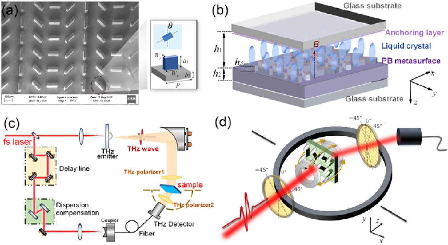
The structure of the LC-PB metadevice is shown in Fig. 1(b). The PB metasurface was fabricated on a high resistance Si substrate of and 1 mm thickness by a photolithography process and reactive ion beam etching with an etching depth of μ. As shown in Fig. 1(a), the Si metasurface is squarely arrayed by the meta-atoms with a period of μ, and four meta-atoms form a supercell along the axis. These four rectangular meta-atoms are of the same size with a length of μ and width of μ, but their long axes are oriented in the plane, and the orientation angles are rotated by in turn. After the Si metasurface was fabricated, two photoalignment anchoring layers were prepared on both the top glass substrate and the surface of the Si metasurface to pre-orient the LC molecules uniformly along the direction. The photoalignment layer was fabricated as follows: 0.4% photoalignment agent SD1 (from JCOPTiX Company, Nanjing, China) was dissolved in N, N-dimethylformamide, followed by spin coating and drying, and finally was exposed by ultraviolet polarized light with at 365 nm [27,37].
Figure 1.(a) SEM image of the Si PB metasurface. Inset: geometry of the meta-atom; (b) geometry of the LC-PB metasurface; (c) optical path diagram of AR-THz-TDPS system; (d) detailed diagram of the experimental setup for time signal measurement with angle resolution and orthogonal polarization detection.
Then, the Si metasurface chip and two fused silica glass sheets were curled as an LC cell by ultraviolet glue, where two custom copper wires with a diameter of 570 μm were placed on the edges of the Si chip as a spacer to ensure the thickness of the LC layer. Then, this LC cell was encapsulated after injecting the LCs. The LCs fill the air gaps of the PB metasurface, and the total thickness of the LC layer μ, exceeding the height of the Si columns. The LC used in this work is a high birefringence nematic LC (HTD028200, from Jiangsu Hecheng Technology Co., Ltd.). The birefringence coefficient of LC is , and the transition temperature from the solid state to the nematic state and from the nematic state to the isotropic state. A pair of hollow electromagnets applies a tunable EMF from 0 to 60 mT along the direction to the metadevice, as shown in Fig. 1(d).
B. Theoretical Analysis
Two pieces of 500 μm thick fused silica glass were used to make LC cells. Each rectangular column in the Si PB metasurface can be seen as a meta-atom with the artificial anisotropic phase difference between the major and minor axes. When the PB meta-atom is typically an HWP with a phase difference of , for the normal incidence of two conjugate photonic spin states (LCP and RCP), the output state will be [38,39] Consequently, this meta-atom will introduce a geometric phase shift dependent only on the rotating angle and to RCP and LCP spin states, respectively, and these spin states will be converted to their spin-flip states (input LCP–output RCP, or RL state; input RCP–output LCP, or LR state).
LC can be seen as an anisotropic material, in which the optical axis can rotate with the external field. In the initial state without the EMF, LC molecules are oriented along the axis under the role of the anchoring layer. If the THz wave propagates along the direction, the LC layer is anisotropic to the wave in this case. The phase shift between RCP and LCP states, where is the thickness of the LC layer. When an EMF is applied along the axis, LC molecules turn from the axis to the axis, and the angle between the long axis of the LC and the axis is defined as . Neglecting absorption and dispersion, the transfer matrix of the LC layer in a circularly polarized basis can be written as follows [40]:
When the LC is integrated with the PB metasurface, the whole transition matrix of the LC-PB meta-atom can be obtained by Eqs. (1) and (2). When the main axis of the LC is along the axis (), should be designed to still meet the conditions of HWP in the broadband range. We design an appropriate LC thickness to satisfy , so that the LC is another equivalent HWP in the same THz range. In this case, the transfer matrix is as follows:
Consequently, the two spin states keep the rotation direction the same, namely, the spin-lock state (input LCP–output LCP, or LL state; input RCP–output RCP, or RR state). But the metasurface still additionally introduces the conjugated geometric phase distribution: and to RCP and LCP states, respectively.
The main axis of the LC is along the axis when the maximum EMF is applied, ; the LC layer displays an isotropic state for the normally incident wave, so . If still meets the conditions of HWP, the transfer matrix can be written as
In this case, the spin conversion and geometric phase of the meta-atom will return to the spin-flip states. According to Eqs. (3) and (4), for the same input spin state, the output spin state and geometric phase are conjugated in just these two states of LC orientations. But in any case, there is always a gradient phase distribution from the PB meta-atoms array, so the spin beam deflections of the metadevice will be dynamically manipulated with the spin state flipping or holding by changing LC orientations. This is the theoretical basis of this work.
3. RESULTS
A. Simulation Results
Numerical simulations are modeled by using the commercial software Lumerical FDTD Solution. The periodic boundary conditions are applied at the and boundaries. The boundaries are surrounded by perfectly matched layers. The refractive index of Si is set to 3.42. The LC layer is modeled as a medium with uniaxial anisotropy and loss, and its extraordinary and ordinary refractive indices ( and ) are set to 1.9 and 1.6 based on the experimental data, respectively. To represent the rotation of the LC optical axis in this work, the dielectric constant of LC needs to be expressed in a tensor form in the simulation. This anisotropic dielectric tensor can take any spatial orientation angle (, ) through a certain orthogonal coordinate transformation from the original diagonal tensor.
The four meta-atoms with LC layers are numbered , as shown in Figs. 2(a) and 2(b). By using FDTD simulations, the transmission spectra of the four spin states (LL, RL, RR, and LR) for the meta-atom (, 2, 3, and 4) can be obtained. As shown in Fig. 2(a), when the LC is along the axis, each meta-atom achieves an efficient and broadband spin flip in the range of 0.75–1.3 THz, that is, realizes an HWP. In this case, the outgoing components are spin-flipped states (RL or LR), and their transmittances are all , but the spin-locked states are all . The device is a typical PB metasurface in this case. The intensity response of the four meta-atoms is the same, and the phase responses are different and follow the law of geometric phase. We obtain the phase shift spectra of the four spin states for the meta-atom (, 2, 3, and 4) relative to , that is, (°). As shown in Fig. 2(c), the two spin-lock states LL and RR have no spatial gradient phase distribution, which means that their outgoing wavefronts are not deflected. For the spin-flip state RL, there is a positive spatial gradient phase distribution in the turn of with a step of 90° in the whole frequency range of 0.4–1.4 THz; the geometric phase difference between two adjacent units is 90°, and the total phase shift is in one PB supercell. Since the geometric phase is broadband with frequency independence, there is no abrupt change in the phase shift spectra as shown in Fig. 2(c). Therefore, for LCP incidence, the RCP outgoing wave will be deflected to the right (the right is defined as a negative deflection angle in this work). For the LR state, there is a negative spatial gradient phase distribution in the turn of with a step of 90°, so the RCP incidence will be converted to the LCP state and deflected to the left as shown in Fig. 2(e).
Figure 2.Simulative transmission spectra of the four spin states (LL, RL, RR, and LR) for four meta-atoms (, , , and ) with different orientations of LC molecules: (a) along the axis and (b) axis. The inset shows the structures of the LC-PB meta-atom in two cycles of the period. Corresponding relative phase shift spectra: (c) LC molecules along the axis and (d) axis. Schematic diagram of the corresponding phase gradient relation, spin states, and deflection direction of the incident wave and outgoing wave with the orientation of LC along the (e) axis and (f) axis.
As shown in Fig. 2(b), when the LC is along the axis, the results become more complicated than the theoretical description in Section 2.B. The transmission and phase responses of each meta-atom are different, and and even have chiral responses, but the whole structure is still symmetric. In the range of 0.75–1.3 THz, the spin state no longer flips, the spin-locked states have high transmittance of , and the spin flips are all or even lower, to . The phase shifts are determined not only by the geometric phase but also by the propagation phases of the meta-atoms. The propagation phase strongly depends on the effect of device resonance. Therefore, when the resonance occurs at the frequency point in Fig. 2(b), there will be an abrupt change in the relative phase shift in Fig. 2(d). For example, the abrupt phase change near 0.7 THz originates from the strong resonance of near 0.7 THz in Fig. 2(b).
As shown in Fig. 2(d), both spin-lock states LL and RR have spatial gradient phase distribution with a step of 90° in the frequency range of about 0.7–1.3 THz. Figure 2(f) shows the details of phase distribution, the wavefront of the LL state is deflected to the left and the RR state to the right. For spin-flip states RL and LR, their relative phase shifts are all in the whole frequency range, so the spatial gradient phase distribution required for beam deflection is not satisfied. The simulation results of phase distribution accord with the theoretical analysis in Eqs. (3) and (4). Figure 3 shows the working functions of the LC-PB metadevice in the different spin incidences and LC orientations. The simulated electric field distributions of the spin states at 1.0 THz are located below the corresponding schematic diagram. We can see that the deflection cases of the simulated electric fields for the four spin states in Figs. 3(a) and 3(c) well confirm the wavefront deflection diagrams in Fig. 2(f) when the LC molecules are along the axis without EMF. When the LC molecules are along the axis with an EMF applied along the axis, the deflection cases of the four spin states in Figs. 3(b) and 3(d) well prove the wavefront deflection in Fig. 2(e). Figures 3(e) and 3(f) show that the diffraction efficiency of the device varies with frequency and deflection angle. For the incident RCP spin state, when the LC is along the axis, the device bends to a negative angle in the range of 0.85–1.1 THz, and the highest diffraction efficiency of 60% is obtained near 1 THz. When the LC turns to the axis, the device is deflected to a positive angle in the range of 0.7–1.1 THz, and the highest diffraction efficiency of 50% is obtained near 0.9 THz. The high diffraction efficiency is determined not only by the quasi-continuous gradient phase distribution, but also by the impedance matching between the LC layer and the Si microstructure. The geometries of the metadevice are optimized by the FDTD simulation with the iterative optimization algorithm. Therefore, this metadevice can actively manipulate beam deflection with spin state conversion.
Figure 3.Schematic diagrams of the LC-PB metadevice in different cases: (a), (b) LCP incidence; (c), (d) RCP incidence. (a), (c) LC molecules along the axis without EMF; (b), (d) LC molecules along the axis with EMF. The simulated electric field distributions of the spin states at 1.0 THz are located below the corresponding diagram. The simulated diffraction efficiency map of the LC-PB metadevice varies with frequency and deflection angle when the RCP is incident: (e) LC molecules are along the axis and (f) axis.
It should also be noted that the phase distribution characteristics of the device are broadband (0.7–1.3 THz) in both LC orientation states, so the beam deflection angle is dependent on the frequency, which meets the following phase-matching condition: , where is the frequency of the THz waves, is the speed of light in vacuum, and μ is the length of one supercell of the PB metasurface. Moreover, the device can spatially separate THz spin beams dependent on the frequencies, and for the two conjugate spin states, they are always spatially separated through the device, so this metadevice can realize both wideband WDM and SDM.
B. Experiment Results
We carry out our experiments by using an angle-resolved THz time-domain polarization spectroscopy (AR-THz-TDPS) system as shown in Figs. 1(c) and 1(d). The THz pulse is generated by one GaAs photoconductive antenna (PCA), and the other fiber-coupled PCA is used for the THz detector. The excitation source is a fiber femtosecond laser of 780 nm with 80 fs duration. All experiments were carried out at room temperature () and relative humidity . The sample is placed at the center of a rotating table, and a parallel THz beam with a diameter of 2 cm is incident on the sample, while the PCA detector is placed on the rotating table to rotate a deflection angle to achieve AR time-domain signal measurement. To focus on the diffraction efficiency of the device itself, we choose to use the empty LC cell as a reference of normalized intensity to the device samples. If the air signal is the reference, the intensity transmittance of the empty LC cell is 70% in the 0.2–1.2 THz range.
To fully investigate the four THz photonic spin states (LL, RL, RR, and LR), it is necessary to input and detect a pair of orthogonal polarization states. Therefore, two THz metallic wire polarizers are placed in front of and behind the sample. The THz polarizer is a metallic grating composed of freestanding metallic tungsten wires with a diameter of 10 μm and spacing of 25 μm. The polarizer has nearly 100% transmittance and more than 99.8% polarization degree in the THz regime. We can measure the four linear co- and cross-polarization transmission coefficients , , , and by rotating both THz polarizers to for a certain deflection angle by our AR-THz-TDPS system. The transmission matrix of the whole device can be obtained as follows [41,42]:
First, we briefly present the THz experimental results for LC without the Si PB metasurface. Here, the LC cell is 500 μm thick, still pre-orientated along the axis, and applies an EMF along the axis. The results in Figs. 4(a) and 4(b) show that when , the LC exhibits anisotropy (i.e., the main optical axis is along the axis) with different amplitudes and phases along and directions, and a phase shift of 180° is obtained near 1 THz. Within the frequency band of 1 THz, the transmittance of both o- and e-light is , which shows a low material loss. When , the intensities in and directions are almost equal, and the phase shift is zero, indicating that the optical axis of the LC is along the axis and the LC is isotropic in the plane. These results prove that the pre-anchoring layer and the EMF of 60 mT are sufficient to drive LC molecules to rotate in the plane.
Figure 4.Experimentally measured THz response of LC without Si PB metasurface: (a) transmission spectra of linear polarization along and directions; (b) birefringence phase shift spectrum between and directions at and 60 mT. Experimentally measured intensity spectra of the four spin states through the bare PB metasurface without LC at (c) positive and (d) negative deflection angles.
Figures 4(c) and 4(d) exhibit the spin beam deflection response of a PB metasurface without an LC layer. The transmittances of all spin-locked states are zero, so they cannot be clearly seen in the figures, and all the transmitted signals are flipped to conjugate spin states. The highest diffraction efficiency of 70% occurs at 0.8 THz for LR deflecting to 27.5° and RL to . The results confirm a typical pure geometric phase metasurface with spin-flip and spin conjugate symmetry described in Eq. (1).
We show the experimental intensity transmission for the four spin states of the LC-PB metadevice at different deflection angles in Fig. 5. When the LC orientation is along the axis with , among the four spin states, only the LL state can detect significant signals at deflection angles from 20° to 32.5° as shown in Fig. 5(a). Its maximum intensity transmittance is 58% at 22.5° corresponding to a central frequency of 1.0 THz, and the intensity on both sides of the deflection angle gradually decreases. The intensity transmittances of the other three spin states are all far less than 10%, so it can be considered that no signal is emitted at these angles. For negative deflection angles from to as shown in Fig. 5(b), only the RR state can be efficiently detected. The intensity transmittance of RR at each deflection angle is equal to that of LL at the corresponding positive deflection angle. This indicates that, in the absence of EMF, the two conjugate spin-lock states are separated at positive and negative deflection angles, and the outgoing beams do not convert. The spin beams with different frequencies are also separated by the different deflection angles followed by the phase-matching condition.
Figure 5.Experimentally measured THz intensity spectra of the four spin states through the LC-PB metadevice at different deflection angles by AR-THz-TDPS: (a) positive deflection angles at ; (b) negative deflection angles at ; (c) positive deflection angles at ; (d) negative deflection angles at .
When the LC orientation turns along the axis with , for positive deflection angles as shown in Fig. 5(c), the signal that can be efficiently detected becomes the LR state. Its maximum intensity transmittance is 50% at 25° corresponding to a central frequency of 0.9 THz, and the intensity on both sides of the deflection angles gradually decreases. Conversely, for negative angles at , only RL states can be detected efficiently as shown in Fig. 5(d). This means that at , the input spin state will be actively converted to its spin-flip state and deflected towards the opposite angle direction. It is worth noting that the deflection angle for optimal deflection efficiency is shifted from 22.5° to 25° (the corresponding frequency also changes), where the efficiency at 22.5° is only 45%, and the maximum efficiency of 50% at 25° is also lower than 58% at 22.5° when . This is because the impedance-matching condition changes with LC orientation. Since the optimal impedance matching of the device structure is designed as the central operating frequency at 1 THz when the LC is oriented along the axis, the optimal matching frequency will shift, and the maximum deflection efficiency decreases when the LC is oriented along the axis. The above experimental results in Fig. 5 well prove the theoretical analysis in Section 2.B and the simulation results in Section 3.A.
To investigate the dynamic process of the device with the increase in EMF, we have also measured the results under intermediate EMFs. Figure 6 shows the intensity spectra of the four spin states varying with the increase in EMF in its deflection direction of the efficient output. As shown in Figs. 6(a) and 6(b), when we input an LCP wave, the output LCP wave comes out at a positive deflection angle at . With the increase in EMF, the output of LCP becomes weaker at , while the output of the RCP state becomes stronger at , indicating that more and more LCP is converted into the RCP state, and the beam energy gradually shifts from a positive to a negative angle. Conversely, as shown in Figs. 6(c) and 6(d), an incident RCP beam outputs the RCP state at the negative angle when , with the increase in EMF; the RR state becomes lower at the negative angle, but its spin-flip state LR becomes stronger at the corresponding positive angle. With this spin conversion, the PB metasurface deflects the output of the spin-flip state to the opposite angle. Therefore, this is not only the dynamic modulation process of two spin states but also the dynamic distribution of beam energy between positive and negative deflection angles.
Figure 6.Experimentally measured THz spectra of the four spin states with the EMF increasing from 0 to 60 mT at the deflection angle of : (a) LL state at 22.5°; (b) RL state at ; (c) LR state at 22.5°; (d) RR state at .
First, we discuss the modulation depth of each spin state with the increase in EMF, which follows , where is the intensity transmittance at different EMFs, and is the intensity transmittance without EMF. Figure 7 shows that the modulation depth of the spin-flip state gradually increases with the increase in EMF. The maximum modulation depths of RL and LR states reach 94.09% and 99.7%, respectively. Similarly, with the increase in EMF, the modulation depths of spin-lock states also increase, and the minus sign indicates that the intensity transmittance decreases from a high to a low value. The maximum modulation depths can reach 98.2% and 96.1% for LL and RR states, respectively. Therefore, the device realizes more than 94% efficient dynamic modulation and an extinction ratio of switching for the four spin states at positive and negative deflection angles by applying a weak EMF of .
Figure 7.Experimental modulation depth of LC-PB metadevice with increasing EMF at : (a) LCP and (b) RCP incidence.
In some application cases, for a certain incident spin state LCP or RCP, we are concerned with only the total output power in a certain deflection angle but do not care about its specific polarization state. We add the total intensities of the spin-lock and spin-flip states together, and , and obtain Fig. 8 from the data in Fig. 5. Because one of the conjugate spin components is always very weak, the shape of the total power line is nearly the same as that of the single spin state. The basic functions of the device remain unchanged as shown in Fig. 3.
Figure 8.Experimental total transmittance spectra of LCP and RCP incidences at all positive and negative deflection angles with or without EMF: (a) LCP incidence at ; (b) RCP incidence at ; (c) LCP incidence at ; (d) RCP incidence at .
However, we also note that despite the broadband characteristics of devices, their efficiency decreases when they deviate from the optimal “frequency-deflection angle”; moreover, some weak signals come from the other side, which we do not expect. This is because ideal HWPs for both LC layers and PB meta-atoms are not perfectly satisfied in a broad THz band, which is difficult to match perfectly in the wide band range in practical devices. Moreover, the LC orientation at 0 T and 60 mT is not perfectly uniform or along the desired direction. All these factors limit the performance of the device. If the incident LCP and RCP spin states carry different information (i.e., SDM), this defect will bring channel cross talk to the information transmission. To characterize the isolation degree of two spin states in spatial angle separation, we define the spin isolation between two spin states as follows: or , where and are the total intensity transmittance of RCP and LCP incidence, and + and − represent the positive and negative deflection directions, respectively. As shown in Fig. 9(a), when , 10.49 dB of isolation can be achieved at for LCP incidence, while 12.27 dB of isolation can be achieved at 20° for RCP incidence. As shown in Fig. 9(b), when , all spin isolations are higher than 10 dB. The maximum value of 16.98 dB is achieved at 25° for the RCP incidence, which means minimal channel cross talk.
Figure 9.Experimental spin isolation of LC-PB metadevice for positive and negative deflection angles at (a) and (b) 60 mT.
In summary, we demonstrated an LC-PB metasurface for THz beam manipulation with spin conversion. The geometric phase of the PB metasurface is matched and controlled by the tunable anisotropic phase shift of LCs; the changes in the spatial gradient phase distribution accompanied by the active spin conversion lead to dynamic beam deflection. The theoretical analyses of the transfer matrix, FDTD numerical simulation, and AT-THz-TDPS experimental characterization have firmly verified the mechanism and functions of this device. The experimental results show that the device realizes efficient dynamic modulation of and diffraction efficiency of for the four different spin states at and 60 mT. Moreover, due to the broadband operating characteristics of devices at 0.7–1.3 THz, the deflection angles are frequency dependent with a scanning range of over to . Furthermore, the two conjugate spin states are always spatially separated in the different deflection directions with most of the spin isolation degrees over 10 dB. Therefore, this metadevice provides a new scheme of active THz beam deflection and spin state conversion and also achieves both controllable WDM and SDM, which have important potential in large-capacity THz space wireless communication.