
Junkang YANG, Kai WANG, Pengcheng ZHAO, Guimei WANG. Design and optimization analysis of a new double-layered tube-type main heat exchanger for lead-bismuth reactors[J]. NUCLEAR TECHNIQUES, 2023, 46(10): 100606
- NUCLEAR TECHNIQUES
- Vol. 46, Issue 10, 100606 (2023)
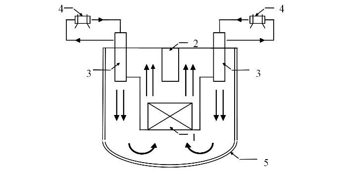
Fig. 1. Schematic diagram of the CLEAR-I structure 1. Reactor core, 2. Central measuring column, 3. Heat exchanger, 4. Air cooler, 5. Safety container

Fig. 2. Heat exchanger composition structure diagram 1. Center downcormer, 2. Double layer heat exchange tube, 3. Shell of heat exchanger, 4. Pressure chamber, 5. Upper tube sheet, 6. Lower tube sheet, 7. Secondary side inlet, 8. Secondary side outlet, 9. Liquid metal inlet window, 10. Liquid metal outlet window, 11. Discharge chamber, 12. Flow distribution device, 13. Secondary side coolant mixing device, 14. Heat shielded housing
Fig. 3. Coolant flow direction diagram
Fig. 4. Variation of the number of heat exchanger tubes with the tube length
Fig. 5. Variation of total heat transfer coefficient with the tube length
Fig. 6. Effect of heat exchanger tube length the on shell-side (a) and tube-side (b) pressure drop
Fig. 7. Effect of heat exchanger tube length on the JF factor
Fig. 8. Variation of total heat transfer coefficient with the outer diameter
Fig. 9. Effect of the outer diameter of heat exchanger tube on shell-side pressure drop (a) and tube-side pressure drop (b)
Fig. 10. Effect of outer diameter of heat exchanger tube on the JF factor
Fig. 11. Variation of total heat transfer coefficient with wall thickness
Fig. 12. Effect of heat exchanger tube wall thickness on tube-side pressure drop
Fig. 13. Effect of heat exchanger tube wall thickness on the JF factor
Fig. 14. Effect of heat exchanger tube spacing on the shell-side pressure drop
Fig. 15. Effect of heat exchanger tube spacing on the JF factor
Fig. 16. Contribution ratio of each parameter
Fig. 17. Variation curve of JF factor (a) and CER (b) factor with number of iterations
|
Table 1. Main thermal-hydraulic parameters of the primary heat exchanger
|
Table 2. Preliminary design parameters of the main heat exchanger
|
Table 3. Design parameter range of the heat exchanger tube
|
Table 4. Comparison of heat exchanger performance before and after optimization

Set citation alerts for the article
Please enter your email address
© Copyright 2018-2021 | Chinese Laser Press. All Rights Reserved 沪ICP备15018463号-20