• Photonics Research
  • Vol. 8, Issue 6, 963 (2020)
Yanliang He1、†, Zhiqiang Xie1、†, Bo Yang1、†, Xueyu Chen1, Junmin Liu2, Huapeng Ye3, Xinxing Zhou4, Ying Li1, Shuqing Chen1、*, and Dianyuan Fan1
Author Affiliations
  • 1International Collaborative Laboratory of 2D Materials for Optoelectronics Science and Technology, and Engineering Technology Research Center for 2D Material Information Function Devices and Systems of Guangdong Province, Institute of Microscale Optoelectronics, Shenzhen University, Shenzhen 518060, China
  • 2College of New Materials and New Energies, Shenzhen Technology University, Shenzhen 518118, China
  • 3Guangdong Provincial Key Laboratory of Optical Information Materials and Technology & Institute of Electronic Paper Displays, South China Academy of Advanced Optoelectronics, South China Normal University, Guangzhou 510006, China
  • 4Synergetic Innovation Center for Quantum Effects and Applications, School of Physics and Electronics, Hunan Normal University, Changsha 410081, China
  • show less
    DOI: 10.1364/PRJ.388838 Cite this Article Set citation alerts
    Yanliang He, Zhiqiang Xie, Bo Yang, Xueyu Chen, Junmin Liu, Huapeng Ye, Xinxing Zhou, Ying Li, Shuqing Chen, Dianyuan Fan. Controllable photonic spin Hall effect with phase function construction[J]. Photonics Research, 2020, 8(6): 963 Copy Citation Text show less
    Shifting the (a) incident position onto the P-B phase metasurface carrying the original phases is equivalent to (b) centrally incident on the P-B phase metasurface carrying the original phase and gradient phase.
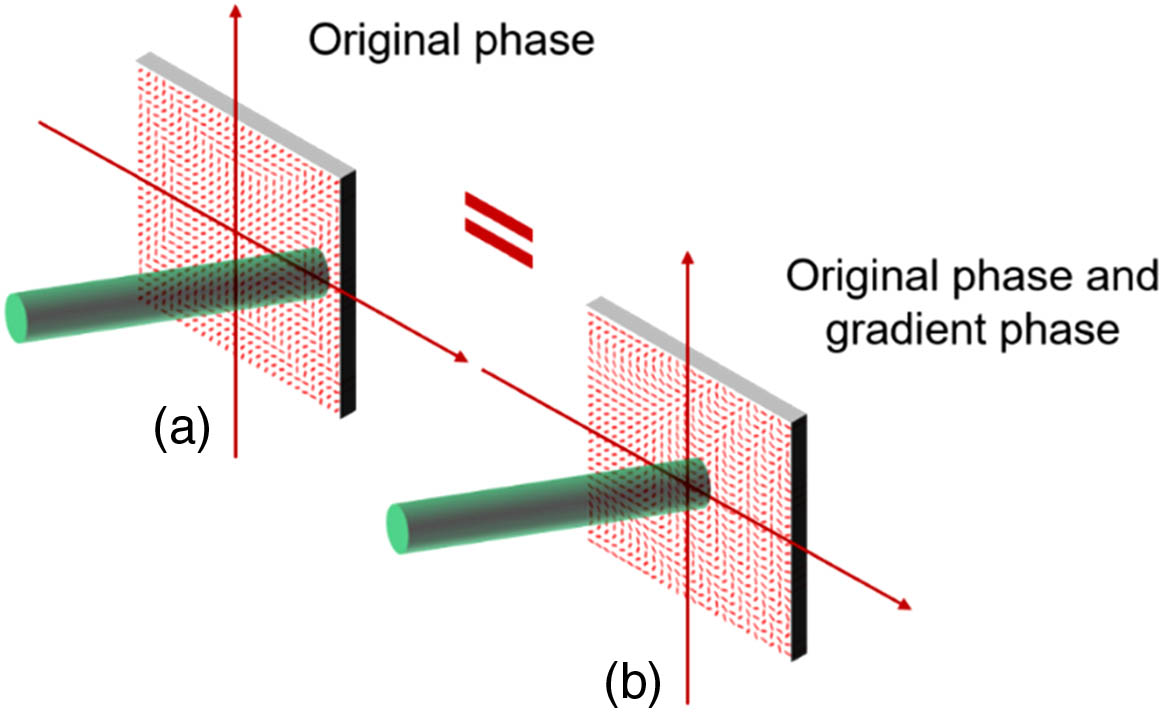
    Fig. 1. Shifting the (a) incident position onto the P-B phase metasurface carrying the original phases is equivalent to (b) centrally incident on the P-B phase metasurface carrying the original phase and gradient phase.
    (I) Illustration of the twisting phase adding together with the gradient phase. (a)–(c) Two-dimensional slow-axis orientation patterns of the twisting phase, gradient phase, and combination phase. (d)–(i) Phases introduced to the LCP and RCP light. (II) Illustration of the lens phase adding together with the gradient phase. (j)–(l) Two-dimensional slow-axis orientation patterns of the lens phase, gradient phase, and combination phase. (m)–(r) Phases introduced to the LCP and RCP light.
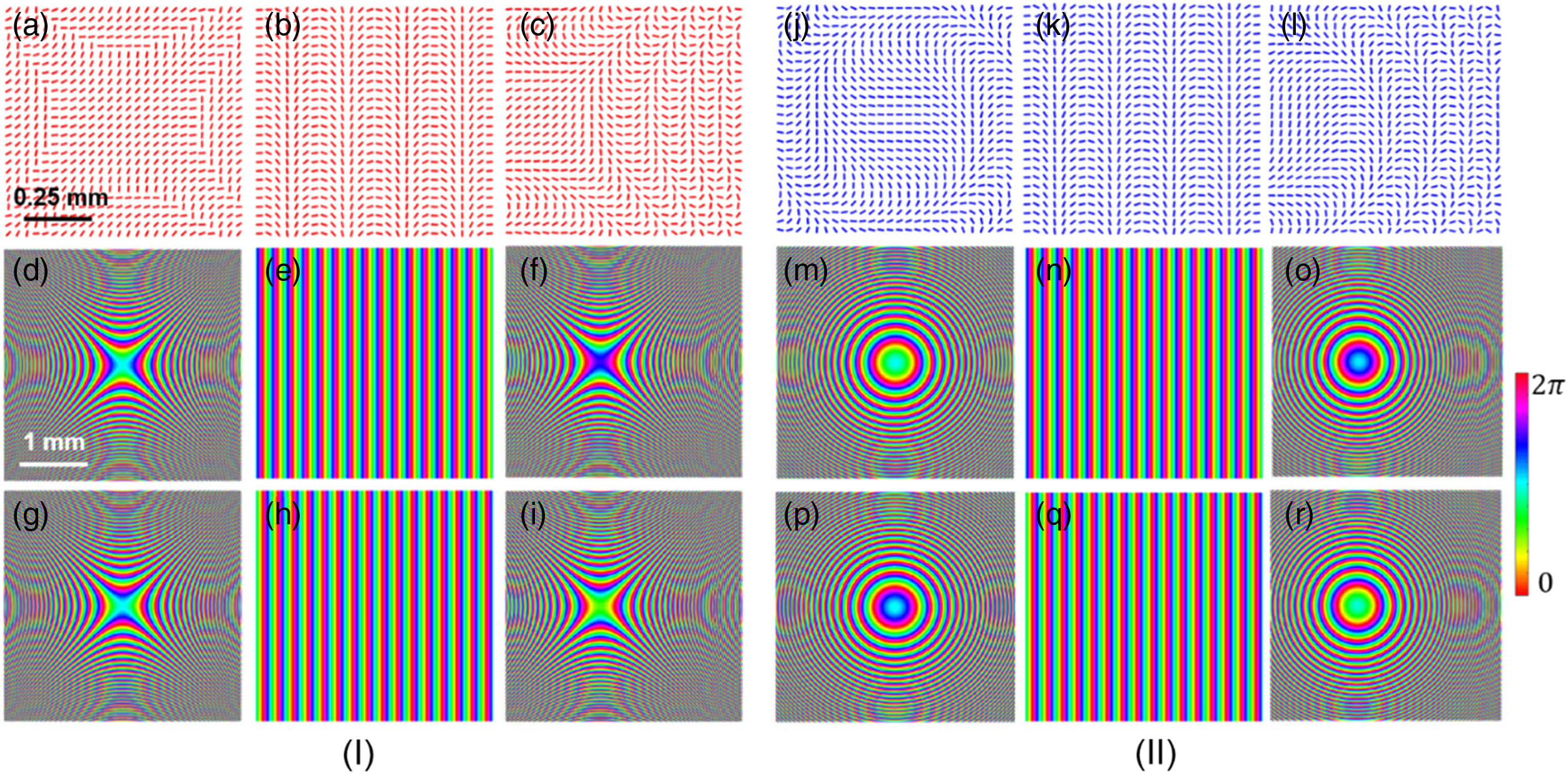
    Fig. 2. (I) Illustration of the twisting phase adding together with the gradient phase. (a)–(c) Two-dimensional slow-axis orientation patterns of the twisting phase, gradient phase, and combination phase. (d)–(i) Phases introduced to the LCP and RCP light. (II) Illustration of the lens phase adding together with the gradient phase. (j)–(l) Two-dimensional slow-axis orientation patterns of the lens phase, gradient phase, and combination phase. (m)–(r) Phases introduced to the LCP and RCP light.
    (a) Illustration of the Gaussian beam illuminating the dielectric P-B phase metasurface. (b) Captured picture of the fabricated metasurface. (c) Polariscopic analysis carried out by optical polarization imaging. (d)–(f) Measured SDS intensity (normalized) images of Gaussian beams at different wavelengths (633, 532, and 475 nm).
    Fig. 3. (a) Illustration of the Gaussian beam illuminating the dielectric P-B phase metasurface. (b) Captured picture of the fabricated metasurface. (c) Polariscopic analysis carried out by optical polarization imaging. (d)–(f) Measured SDS intensity (normalized) images of Gaussian beams at different wavelengths (633, 532, and 475 nm).
    (a) Measured Stokes parameters S3 of the linearly polarized Gaussian beams at the incident position shifts of ±0.9,±1.2, and ±1.5 mm. (b) and (c) Intensity curves corresponding to the white dashed lines across the intensity images at the incident position shifts of ±0.60,±0.75,±0.90,±1.05,±1.20, and ±1.35 mm.
    Fig. 4. (a) Measured Stokes parameters S3 of the linearly polarized Gaussian beams at the incident position shifts of ±0.9,±1.2, and ±1.5  mm. (b) and (c) Intensity curves corresponding to the white dashed lines across the intensity images at the incident position shifts of ±0.60,±0.75,±0.90,±1.05,±1.20, and ±1.35  mm.
    Measured intervals between LCP and RCP components with different incident position shifts at the transmission distance of 500 mm. Cal., calculated; Exp., experimental.
    Fig. 5. Measured intervals between LCP and RCP components with different incident position shifts at the transmission distance of 500 mm. Cal., calculated; Exp., experimental.
    Measured ellipticities versus the incident polarization (a function of β). (a)–(f) Optical intensity (normalized) profiles correspond to situations of β=45°,75°,85°,95°,105°, and 135° at the wavelength of 633 nm. Cal., calculated; Exp., experimental.
    Fig. 6. Measured ellipticities versus the incident polarization (a function of β). (a)–(f) Optical intensity (normalized) profiles correspond to situations of β=45°,75°,85°,95°,105°, and 135° at the wavelength of 633 nm. Cal., calculated; Exp., experimental.
    (a) Schematic diagram of the experimental setups of arbitrarily singular beams detection based on the geometric P-B phase metasurface. P, polarizer; QWP, quarter-wave plate; MS, metasurface; FL, Fourier lens; CCD, charge-coupled device. (b) Measured S3 parameters of the output beams with different transmission distances (z=100, 200, 300, 400, and 500 mm).
    Fig. 7. (a) Schematic diagram of the experimental setups of arbitrarily singular beams detection based on the geometric P-B phase metasurface. P, polarizer; QWP, quarter-wave plate; MS, metasurface; FL, Fourier lens; CCD, charge-coupled device. (b) Measured S3 parameters of the output beams with different transmission distances (z=100, 200, 300, 400, and 500 mm).
    (a) and (b) Experimental results of the VBs (the topological charges are 1 and 2) diffracting through the metasurface. (c) and (d) Experimental results of the CVBs (the polarization orders are −1 and 2) diffracting through the metasurface. (e) and (f) Experimental results of the CVVBs [the topological charges and polarization orders are (1, 2) and (2, −1)] diffracting through the metasurface. The gray lines represent the theoretical polarization profiles.
    Fig. 8. (a) and (b) Experimental results of the VBs (the topological charges are 1 and 2) diffracting through the metasurface. (c) and (d) Experimental results of the CVBs (the polarization orders are 1 and 2) diffracting through the metasurface. (e) and (f) Experimental results of the CVVBs [the topological charges and polarization orders are (1, 2) and (2, 1)] diffracting through the metasurface. The gray lines represent the theoretical polarization profiles.
    Yanliang He, Zhiqiang Xie, Bo Yang, Xueyu Chen, Junmin Liu, Huapeng Ye, Xinxing Zhou, Ying Li, Shuqing Chen, Dianyuan Fan. Controllable photonic spin Hall effect with phase function construction[J]. Photonics Research, 2020, 8(6): 963
    Download Citation