
Jiajun Ma, Chunmei Ouyang, Yuting Yang, Xinyue Qian, Li Niu, Yi Liu, Quan Xu, Yanfeng Li, Zhen Tian, Jianqiang Gu, Jiaguang Han, Weili Zhang. Frequency-dependent selectively oriented edge state topological transport[J]. Advanced Photonics Nexus, 2024, 3(3): 036004
- Advanced Photonics Nexus
- Vol. 3, Issue 3, 036004 (2024)
Abstract
Keywords
1 Introduction
Topological insulators, a new phase of matter supporting energy conduction along the edges while behaving as an insulator in the bulk, have attracted intense interest from condensed matter physics1
A variety of TPCs have been developed subsequently to mimic the quantum Hall effect,18
Photonic bandgaps (PBGs) are a crucial feature of photonic crystals,45,46 widely applied in optical communication and optoelectronic devices. As the EM waves propagate in periodic structures and are influenced by Bragg and Mie scattering, PBGs are formed between energy bands, and the EM waves within the PBGs will be strongly reflected and cannot propagate in these structures. Unlike a common PBG for bulk modes in fully periodic photonic crystals, the PBG between the edge and bulk states in a valley TPC is unique: EM waves within the special PBG cannot propagate either in the bulk region or along the interface. Notably, most previous studies have been focused on the robustness of the edge states, neglecting the importance of the PBGs. In most previously proposed valley TPCs, the topological edge states and bulk states are continuous, and no special PBG emerges between the edge and bulk states, which limits the promising applications of these valley TPCs in frequency filtering, division, and multiplexing.47
Sign up for Advanced Photonics Nexus TOC. Get the latest issue of Advanced Photonics Nexus delivered right to you!Sign up now
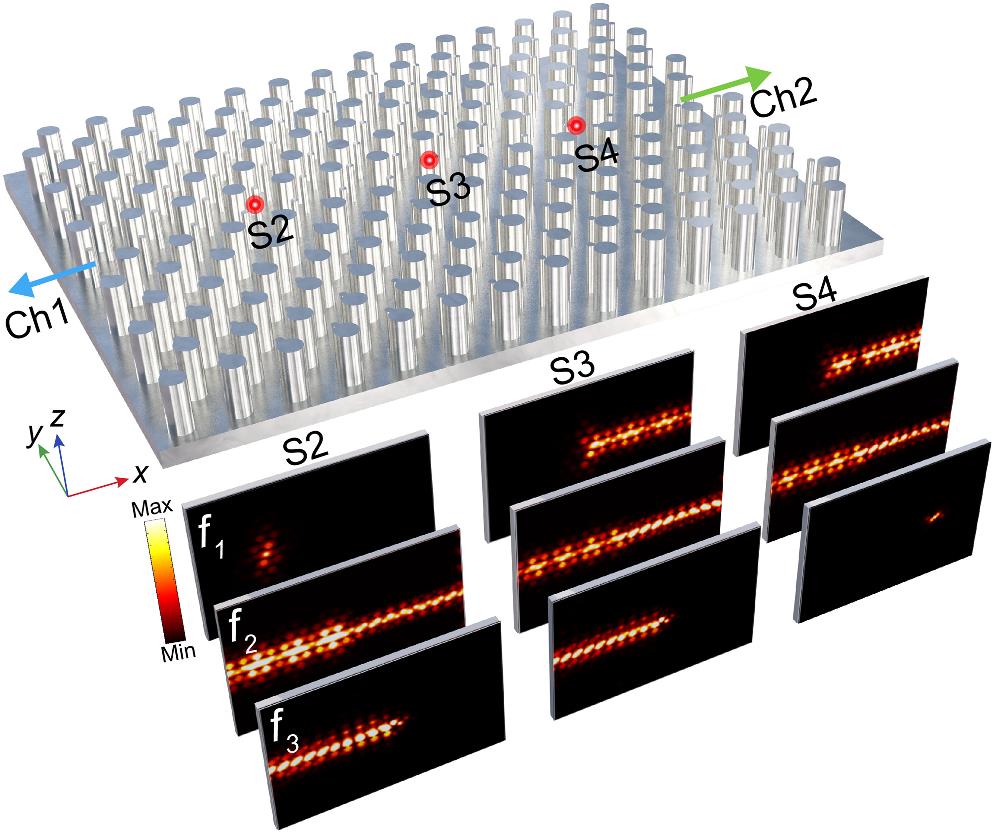
In this work, we introduce the concept of the threshold value in PBG theory to valley TPCs and clearly establish the relationship between the degree of symmetry breaking and the working bandwidth of the edge states and PBGs. Specifically, broadband spoof surface plasmon polariton (SPP) valley TPCs with edge states and PBGs are proposed. Not only do the broadband edge states detach from bulk states and exhibit PBGs, but the spoof SPP edge states are also protected and self-confined in the x-y plane. Furthermore, a broadband frequency-dependent selectively directional transmission (FSDT) topological photonic device is designed and experimentally demonstrated by stacking spoof SPP valley TPCs with different working frequencies, as schematically shown in Fig. 1. The FSDT device exhibits an intriguing frequency multiplexing feature, where edge states in different frequency ranges selectively transport in different edge channels. This functionality enables near-field wavelength division multiplexing (WDM) and add–drop multiplexing (ADM) when the excitation source is located at different locations. These results will enrich the understanding of fundamental physics underlying topological photonics and help design and construct novel topological photonic devices.
![]()
Figure 1.Schematic of the FSDT topological photonic device, which has the intriguing frequency multiplexing feature that edge states of different frequencies selectively transport in different edge channels.
2 Results
2.1 Broadband Spoof SPP Valley TPCs
The proposed spoof SPP valley TPCs with topological edge states and engineered PBGs consist of aluminum rods of different heights and radii on top of a metal surface, as shown in Fig. 2(a). Due to the periodic metallic structures,55 spoof SPP topological edge states are supported to propagate on the metallic valley TPCs, where the energy is localized at the metallic surface and exponentially decays in both the vertical and transverse directions, and thus the spoof SPP edge states cannot radiate into free space and are self-confined. This means that the proposed design here does not need a covering lid and possesses the extra degree of freedom of modifying the height of the rods to tune the working frequency and broaden the working bandwidth, which does not affect the size or layout of the structure. In addition, compared with other domain walls, the robustness and bandwidth of the edge states along the zigzag-shaped domain wall are wider.56Figure 2(a) shows that our proposed spoof SPP valley TPC is composed of valley photonic crystals (VPCs) with inverted symmetry along the zigzag domain wall. Each unit cell of the VPCs contains two rods of different heights and radii with a lattice constant . The height and radius of rod 1 are and , respectively, and those of rod 2 are and , respectively. When these two rods have a uniform height and radius (that is, and ), the VPCs exhibit symmetry that leads to a Dirac dispersion near the points in the simulated band diagram at 5.00 GHz [blue dotted lines in Fig. 2(b)]. Note that the valleys are located well below the light line in the air [black lines in Fig. 2(b)]; thus, spoof SPP modes in the neighborhood of the Dirac points can be supported on the VPCs. Then upon breaking the inversion symmetry by simultaneously turning on the height difference and radius difference , the Dirac degeneracies are removed and a complete PBG () is opened [red solid lines in Fig. 2(b)].
![]()
Figure 2.Broadband spoof SPP valley TPCs. (a) Schematic illustration of the designed TPC structure composed of VPCs with inverted symmetry, where the rhomboidal unit cell consists of inequivalent metallic rods with different radii and heights on top of a metal surface. The green line denotes the zigzag-shaped domain wall. (b) Band diagram of the VPCs with and without inversion symmetry, where the blue, red, and black lines represent the dispersions of the VPCs with inversion symmetry, without inversion symmetry, and the light line in air, respectively. The light-yellow region corresponds to the common PBG of the VPCs. Left inset: first Brillouin zone of the VPCs. (c) Simulated eigenmode profiles at
The corresponding distributions of the -oriented electric field profiles and Poynting power flow of the modes at the () valleys after the perturbation are illustrated in Fig. 2(c). There are four modes that exhibit either left-handed circular polarization or right-handed circular polarization. In addition, within the same band, the polarizations of these modes are opposite at and valleys. It is known that VPCs feature nonzero Berry curvatures accumulated around different valleys. We find that the valley numbers are half-integers,57 () for the first band, and () for the second band. Thus, the difference between the valley Chern numbers at () points across the zigzag-shaped domain wall in the valley TPCs formed by combining two VPCs with opposite half-integer valley Chern numbers is . According to the bulk-boundary correspondence, it is expected that valley topological edge states will emerge at the domain wall in the valley TPCs within the original PBG of the VPCs.
Then, we numerically calculate the band diagram projection for a supercell; the results are shown in Fig. 2(d), where a broadband topological edge state (red-shaded region) is found to be localized at the domain wall, whose propagating directions are locked to the and valleys. Interestingly, it should be noted that the edge mode bands are detached from the bulk bands (black lines): a special PBG1 (light blue region) is found. PBG2 also appears above the upper bulk band [see Fig. 2(d)], and according to the band diagram of the unit cell and the dispersion relation of the supercell, it can be seen that it has no relationship with the perturbation , and it is always present (see section 1 in the Supplementary Material). Note that the upper bulk bands are flat and cover a very narrow frequency range, so they are difficult to excite, functioning like a bandgap in the experiments. Thus, the valley edge states are separate from the bulk bands on both sides, which can be effectively viewed as being sandwiched by two bandgaps (PBG1 and PBG2). This is a unique feature that has not been observed previously in any other topological materials.
To further confirm the mechanism of the emergence of the special PBG1 between the edge and bulk states and the quantitative relationship between the bandwidth of the edge states and the degree of symmetry breaking, we systematically investigate the relationship between the perturbation ( and ) and the edge states and PBGs, including the common PBG in the VPCs, the special PBG1, and the edge states in the valley TPCs, as shown in Figs. 3(a) and 3(b). It can be seen that for the common PBG in the VPCs, its bandwidth generally increases monotonically with the perturbation ; for the edge states in the TPCs, the bandwidth also increases monotonically with . However, the rate of increase of the edge state bandwidth decreases with when the perturbation is larger than a value (called the threshold value ). For the special PBG1 in the TPCs, when , the bandwidths of the VPC-PBG and TPC-edge states vary synchronously with the perturbations and are equal, which is to say that there is no special TPC-PBG1 in this case. When , as the growth rate of the VPC-PBG is larger than that of the TPC-edge states, the special TPC-PBG1 emerges, and its bandwidth also increases monotonically with . The concept of the threshold value is derived from the PBG theory,58 which states that there is no PBG until the dielectric contrast is increased to some threshold value. Above this threshold, the bandgap opens up and its width usually increases monotonically with the dielectric contrast. Since the dielectric contrast in the valley TPCs is governed by the perturbation (see section 2 in the Supplementary Material), we can conclude that the PBG in the valley TPCs is influenced by the perturbation as well. The threshold values of opening the same PBG in different ways are different: the threshold values of changing the height difference and radius difference to open PBG1 are and , respectively. The results presented in Figs. 3(a) and 3(b) illustrate that the valley TPCs with a large enough perturbation not only have broadband edge states but also have a special PBG between the edge and bulk states. It is worth mentioning that in this work we achieve large enough perturbation by simultaneously adjusting the height difference and radius difference of the different rods that constitute the proposed valley TPCs.
![]()
Figure 3.Valley topological edge states and PBGs. (a) and (b) Evolution of the working bandwidths of the VPC-PBG, TPC-edge states, and TPC-PBG1 with respect to the perturbations of height difference
Then, the transmission spectrum of the spoof SPP valley TPCs is simulated and displayed in Fig. 3(c). In the simulation, a dipole source is placed at the left end of the domain wall to excite the edge states, and a probe at the right end of the domain wall is used to measure the transmission spectrum. The simulated transmission band of the edge states and PBG1 in Fig. 3(c) matches well with the frequency range of the calculated dispersion for the ribbon-shaped supercell in Fig. 2(d). We can also observe a PBG1 between 4.60 and 4.94 GHz, the edge states between 4.94 and 5.40 GHz, and the ever-present PBG2. The simulated field distributions of the valley topological edge states in the x-y, x-z, and y-z planes at 5.20 GHz are shown in Fig. 3(d), demonstrating that the edge states are evanescently decaying and well confined at the domain wall in both the vertical and transverse directions. It can be seen that the proposed valley TPCs support the propagating spoof SPP topological edge states.
2.2 Multifunctional FSDT Topological Photonic Device
The proposed spoof SPP valley TPCs have the advantages that not only the edge mode bands are detached from the bulk bands and a special PBG emerges but also the working frequency is easily tuned by modifying the height of the rods, which does not affect the size or layout of the structure. Taking advantage of this exotic feature, we proceed to design a broadband multifunctional FSDT topological photonic device, which has an intriguing feature: novel frequency multiplexing of different frequency edge states transporting in different edge channels can be achieved. Figure 4(a) shows the design strategy of the FSDT device, which consists of two spoof SPP valley TPC waveguides with different heights (TPC I and TPC II). The dispersion relations of the edge states for TPC I and TPC II are marked by the blue and red lines in Figs. 4(c) and 4(d), respectively. Clearly, by carefully optimizing the structural parameters of TPC I and TPC II, the frequency ranges of the edge states and PBGs can both be adjusted to the desired state, as shown in Figs. 4(c) and 4(d) (for more details on TPC I and TPC II, see section 3 in the Supplementary Material). Note that, for this FSDT topological photonic device, the armchair domain wall between TPC I and TPC II along the axis cannot support topological interface modes because the valley Chern number across the armchair domain wall is zero (see section 4 in the Supplementary Material).
![]()
Figure 4.Concept of the broadband FSDT topological photonic device. (a) Design strategy of the FSDT device composed of two valley TPCs with different heights
The composite device could achieve the following functions through the combined action of valley edge states and PBGs in two valley TPCs, as shown in Fig. 4(b). The spoof SPP topological edge states in the high-frequency (HF) regime propagate only along the domain wall of TPC I [light blue region in Fig. 4(a)]; in the intermediate-frequency (IF) regime, bidirectional transmission along the domain walls of TPC I and TPC II can be achieved [light yellow region in Fig. 4(a)]; and the low-frequency (LF) waves transmit only along the domain wall of TPC II [light red region in Fig. 4(a)]. Therefore, the device has the functions of WDM and ADM when the excitation source is located at different locations. For example, when the source is located at the center between TPC I and TPC II or in the middle of TPC I and the middle of TPC II, the WDM and ADM functions can be achieved, respectively. Note that in previous valley TPCs, the topological edge states and bulk states are continuous and cannot be used to realize the FSDT device, as demonstrated in section 5 in the Supplementary Material.
To demonstrate the capability of the broadband FSDT topological photonic device based on the proposed valley TPC structures, we have fabricated a finite-sized sample consisting of unit cells, as shown in Fig. 5(a). It is composed of aluminum rods of different heights and radii and a metallic substrate, which is fabricated with the traditional metal machining technique. The substrate is 10 mm thick and has corresponding 5-mm air holes, and the aluminum rods are assembled on the metallic substrate. In the experiment, the transmission spectra and field distributions are directly measured by a scanning near-field microwave microscopy system without an extra metallic cover due to the fact that the proposed valley TPCs support the propagation of the spoof SPP topological edge states. A coaxial monopole antenna is placed in the drilled holes of the metallic substrate at ports S2, S3, and S4 to excite the spoof SPP topological edge states, whereas another probe antenna is fixed on a scanning support to measure the transmission spectra and scan the near-field electric field distributions.
![]()
Figure 5.Experimental observation of the broadband FSDT device. (a) Photograph of the experimental sample of the topological photonic device, which is composed of TPC I and TPC II. The blue and red lines represent the positions of the domain walls of TPC I and TPC II, respectively. (b)–(d) Experimentally recorded transmission spectra (in dB) at ports S1 and S5 when the source is placed at ports S3, S2, and S4, respectively. The transmission spectrum corresponding to port 1 is shown as the solid blue line, while that for port 5 is shown as the solid red line. The insets on the right in each figure are the experimental
When the device is excited from the center port S3 between TPC I and TPC II, the measured transmission spectra and electric field distributions indicate that the WDM function is realized in the experiments, as shown in Fig. 5(b). It can be seen that the IF and HF EM waves within 5.06 to 5.70 GHz propagate to the left along the domain wall of TPC I, and the LF and IF EM waves within 4.72 to 5.38 GHz transmit to the right along the domain wall of TPC II. The inset on the right describes the experimentally measured electric field distributions at 4.88, 5.13, and 5.44 GHz. The edge states at 5.44 GHz (HF region) propagate unidirectionally to the left along the domain wall of TPC I, the edge states at 5.13 GHz (IF region) propagate bidirectionally along the domain walls of TPC I and TPC II, and the edge states at 4.88 GHz (LF region) transmit one-way to the right along the domain wall of TPC II. The robustness of the FSDT device is shown in section 6 in the Supplementary Material.
When the source is located at ports 2 and 4, the measured transmission spectra and electric field distributions are depicted in Figs. 5(c) and 5(d), respectively, illustrating an ADM function. When the excitation source is placed at port 2, the detection receiver at ports 1 and 5 can receive IF and HF waves within 5.09 to 5.61 GHz and IF waves within 5.09 to 5.34 GHz, respectively. When the excitation source is placed at port 4, the detection receiver at ports 1 and 5 can receive IF waves within 5.09 to 5.34 GHz and LF and IF waves within 4.83 to 5.34 GHz, respectively. Overall, the experimental measurements of the transmission spectra and electric field distributions are in good agreement with the simulations. However, the experimental equipment, sample fabrication, and environmental conditions cause a slight difference in the frequencies between the experimental and simulated results (for more simulation details, see section 7 in the Supplementary Material).
3 Discussion and Conclusion
In summary, we have introduced the concept of threshold value in PBG theory to valley TPCs and described the relationship between the perturbation and the working bandwidth. On this basis, a broadband spoof SPP valley TPC with broadband edge states and engineered PBGs is proposed. In addition, benefiting from the property of the edge states support while the PBGs forbid EM wave transmission, we fabricate and experimentally demonstrate an FSDT topological photonic device in the microwave regime by stacking two valley TPCs with different frequencies. The device can achieve the functions of WDM and ADM when the excitation source is located at different positions.
Our results are of significance not only in understanding the fundamental physics underlying topological photonics but also in offering useful insights and solutions to design novel topological photonic devices that can be utilized in constructing frequency filtering and splitting devices. Besides, similar ideas can be generalized not only to the terahertz range for 6G wireless communications and the optical range for optical communications but also to other wave systems.
Furthermore, the proposed spoof SPP valley TPCs with broadband edge states and engineered PBGs have more EM properties than most previous valley TPCs. Meanwhile, the working frequency of the valley TPCs can be easily tuned by adjusting the height without interfering with other parameters, which is convenient to adjust and could be applied to active control.
4 Appendix: Experimental Section/Methods
4.1 Sample Fabrications
Our FSDT sample was fabricated with the traditional metal-machining technique. It is composed of aluminum rods of different heights and radii and a metallic substrate. The substrate is 10 mm thick and has corresponding 5-mm air holes, and the aluminum rods are assembled on the metallic substrate.
4.2 Experimental Characterization
A scanning near-field microwave microscopy system was employed to measure the transmission spectra and near-field electric field distributions. The system comprises a vector network analyzer (Keysight E5063A) and a three-dimensional scanning platform. Two coaxial probes act as the emitting antenna and probe antenna, respectively. The emitting antenna is placed in the drilled holes of the metallic substrate at ports 2, 3, and 4 to generate the valley edge states, whereas the probe antenna is fixed on a scanning support to measure the transmission spectra and scan the near-field electric field distributions.
4.3 Numerical Simulations
The dispersion relations of the spoof SPP valley TPCs are numerically obtained in the frequency domain with the commercial finite-element method-based software COMSOL Multiphysics. The projected band diagrams are evaluated using a supercell containing 10 unit cells on either side of the domain wall, and periodic boundary conditions are imposed on the left and right sides. The simulations of the transmission spectra and field distributions are performed with the time domain solver of CST Microwave Studios. Open boundary conditions are applied in all directions, and the materials of the valley TPCs are set as perfect electric conductors.
Jiajun Ma received his BS degree in optical engineering from Tianjin University, China, in 2021. Currently, he is working toward his PhD in optical engineering at the Center for Terahertz Waves, Tianjin University, China. His research interests focus on topological functional devices and microwave photonics.
Chunmei Ouyang is an associate professor at Tianjin University, China. She received her BEng degree in electronic science and technology, her MEng degree in optical engineering from Harbin Engineering University, China, in 2003 and 2005, respectively. She received her PhD in opto-electronics technology from Tianjin University, China, in 2009. She has published more than 100 peer-reviewed journal papers with total citation of ∼2300 (H index is 24). Her current research interests focus on intense terahertz source, topological functional devices, and terahertz subwavelength devices.
Biographies of the other authors are not available.
References
[2] J. E. Moore. The birth of topological insulators. Nature, 464, 194-198(2010).
[6] Z. Yang et al. Topological acoustics. Phys. Rev. Lett., 114, 114301(2015).
[8] X. Zhang et al. Topological sound. Commun. Phys., 1, 97(2018).
[9] B. Hu et al. Non-Hermitian topological whispering gallery. Nature, 597, 655-659(2021).
[10] H. Xue, Y. Yang, B. Zhang. Topological acoustics. Nat. Rev. Mater., 7, 974-990(2022).
[11] M. C. Rechtsman et al. Photonic Floquet topological insulators. Nature, 496, 196-200(2013).
[12] A. B. Khanikaev et al. Photonic topological insulators. Nat. Mater., 12, 233-239(2013).
[15] T. Ozawa et al. Topological photonics. Rev. Mod. Phys., 91, 015006(2019).
[16] Z. Chen, M. Segev. Highlighting photonics: looking into the next decade. eLight, 1, 2(2021).
[25] S. Barik et al. A topological quantum optics interface. Science, 359, 666-668(2018).
[31] J.-W. Liu et al. Valley photonic crystals. Adv. Phys.: X, 6, 1905546(2021).
[34] P. Zhou et al. Photonic amorphous topological insulator. Light Sci. Appl., 9, 133(2020).
[58] J. Joannopoulos et al. Photonic Crystals: Molding the Flow of Light(2008).

Set citation alerts for the article
Please enter your email address
© Copyright 2018-2021 | Chinese Laser Press. All Rights Reserved 沪ICP备15018463号-20