Fifth-generation (5G) communication requires spatial multiplexing multiple-input multiple-output systems with integrated hardware. With the increase in the number of users and emergence of the Internet of Things devices, complex beamforming devices have become particularly important in future wireless systems to meet different communication requirements, where independent amplitude and phase modulations are urgently required for integrated beamforming devices. Herein, by utilizing the constructive interference between multiple geometric-phase responses, the mathematical relation for decoupling amplitude and phase modulations in the radiation-type operational mode is derived. Based on this strategy, complex-amplitude radiation-type metasurfaces (RA-Ms) are implemented, with an integrated feeding network. Such metasurfaces exploit full phase modulation and tailorable radiation amplitude in the circular polarization state. Meanwhile, a complex-amplitude retrieval method is developed to design the RA-Ms, enabling precise beamforming performances. On this basis, several functional devices based on the complex-amplitude RA-Ms, including energy-allocable multi-router, shape-editable beam generator, and complex beamformer, are demonstrated in the microwave region. The amplitude-phase decoupling mechanism with the retrieval method merges amplitude and phase modulations, and energy distribution into one compact and integrated electromagnetic component and may find applications in multi-target detection, 5G mobile communication, and short-range ground-to-sea radar.
1. INTRODUCTION
Metasurfaces, the customized planar arrays composed of subwavelength meta-atoms, have attracted significant attention in microwave, terahertz, and optical regions due to their fabrication ease and powerful capabilities. Multiple electromagnetic (EM) characteristics, including amplitude, phase, polarization, and frequency, can be manipulated via metasurfaces with the transmissive-type or reflective-type operational mode. To date, metasurface-based platforms have emerged as promising alternatives for a series of practical applications, such as metalenses [1–5], invisibility cloaks [6–10], beam deflection [11–15], holography [16–21], and orbital angular momentum (OAM) generators [22–26]. With further developments of highly compact and precise systems, more critical demands are imposed on the metasurface-based components. However, despite the enriched modulation capability and subwavelength profile of metasurfaces, the necessary external feeds significantly limit the improvement in system complexity and overall longitudinal dimension, both for transmissive-type metasurfaces and reflective-type ones.
To overcome this issue, many mentalities of designs are proposed, which mainly focus on narrowing the feeding path length. Based on the folded ray-tracing principle, the folded-reflectarray (FRA) and folded-transmitarray (FTA) are introduced, which usually consist of three parts, i.e., the feed, the reflector, and the polarization grid. Compared with the conventional non-folded mode with the focal length , the profile of an FRA or FTA can be decreased to . Recently, various functional FRA and FTA have been reported, including frequency-multiplex, OAM generation, and beam shaping and steering [27–30]. Also, Fabry–Perot-type metasurface, composed of a ground plane, a partially reflective surface, and a feed antenna located in the resonant cavity, can be a good strategy for low-profile design. The height of the Fabry–Perot cavity is usually set as half of the operational wavelength, thus achieving low-profile properties. The Fabry–Perot-type metasurface has found many applications in high-gain low-profile antennas [31,32]. However, in the methods aforementioned, complete feed integration is still not available, which limits the further compression of the overall longitudinal dimension [33]. Additionally, the feed antenna tends to have a sophisticated design process, especially in the case of circular polarization [34]. Therefore, achieving arbitrary EM wavefront manipulation in one self-feeding component, consisting of the radiating element and the attached excitation, is of great interest for the miniaturization and integration of systems.
Initially, the self-feeding metasurface was reported in Refs. [35,36] via the combination of metasurface and phased array units. More recently, many attempts have focused on radiation-type metasurfaces (RA-Ms) in which flexible wave modulation and low-profile geometry can be simultaneously implemented. Such RA-Ms generally consist of the upper radiating element, the microstrip power division network on the back, and the via hole for conduction. The guided EM energy is fed evenly to each meta-radiator through the power division network. By subsequently tuning the upper structure to adjust the surface current path, the radiating element can achieve arbitrary phase shift, realizing the desired EM wavefront. The RA-Ms integrate the functions of the guided-radiated wave converter and the phase shifter, which greatly improve compactness and cost of EM devices compared to phased array. Advanced phase modulation devices are thus realized. The authors of Refs. [37–39] reported discrete phase modulation by adjusting the phase delay lines in the feeding network. Further, continuous phase modulation, based on Pancharatnam–Berry (PB) phase response, was proposed in Ref. [40], and a series of functions, including multi-beam generation and radar cross-section reduction, were demonstrated. To integrate more degrees of freedom (DoFs) in one RA-M, the work in Ref. [41] synthesized PB response and feeding-line phase delay and achieved independent phase and polarization control. By altering the resonant phase additively, tailorable energy allocation between cross- and co-channel can be realized [42]. In addition, a programmable RA-M was proposed to achieve a reconfigurable beam scanning function [43]. Enabling abundant wave modulation within the subwavelength longitudinal profile, RA-Ms provide an effective alternative to reflective-type and transmissive-type ones. However, the complex-amplitude modulation is unexploited in the reported RA-Ms, resulting in a compromised signal-to-noise ratio in many image-display scenarios and difficulties in complex beam generations. Compared to phase-only metasurfaces, complex-amplitude metasurfaces own superior wavefront modulation, where the former tends to seek complicated and laborious optimization for help, and the latter is not only capable of directly achieving the modulation via the theoretical formulas but also having faster and precise modulation ability when it comes to optimization algorithms [44,45]. The additional DoF of EM precise manipulation has ensured complex-amplitude metasurfaces for a wider range of applications such as high-quality holograms [46], non-linear EM wave control [47], and adaptive manipulation devices [48]. Therefore, implementing simultaneously independent amplitude and phase modulation in the radiation-type operational mode is still challenging and of great research significance for versatile, miniaturized, and integrated systems.
Sign up for Photonics Research TOC. Get the latest issue of Photonics Research delivered right to you!Sign up now
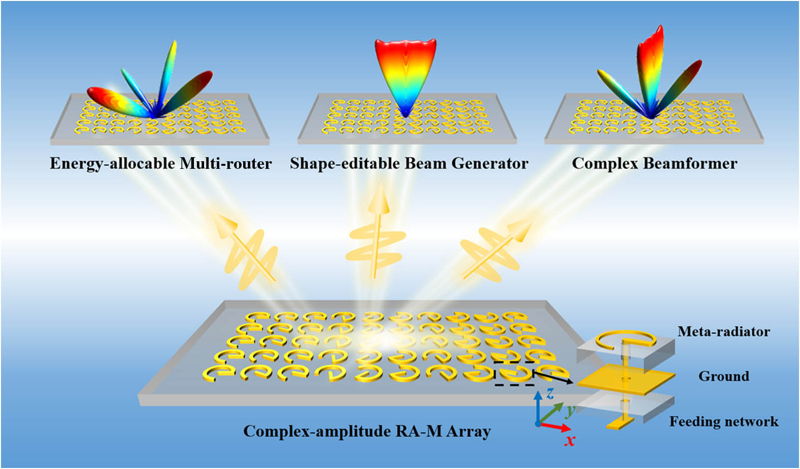
Here, we propose a complex-amplitude modulation strategy for constructing an RA-M enabling full phase modulation and tailorable radiation amplitude in the circular polarization state. The constructive interference between multiple geometric-phase responses is utilized to decouple the amplitude and phase modulation, and the mathematical relation between multiple geometric-phase and complex-amplitude modulation decoupling is derived. Accordingly, a single-layer meta-radiator for constructing the metasurface is proposed, which is simply interleaved by two geometric-phase elements with independent in-plane rotation. Moreover, a far-field complex-amplitude retrieval (FCAR) method is developed for implementing advanced beamforming with energy allocation and shape editing functions. As proof-of-concept, several functional devices, including energy-allocable multi-router, shape-editable beams generator, and complex beamformer, are designed and fabricated for verification in the microwave region, as schematically shown in Fig. 1. This proposed strategy may open new avenues for metasurfaces with multiple dimensional wavefront manipulations and miniaturized profiles and can be readily realized also in other frequency regions.
Figure 1.Schematic function demonstration of the proposed complex-amplitude RA-M. Beams with different characteristics can be obtained based on the proposed strategy. The inset illustrates the detailed structure of the meta-radiator in the dashed box.
First, from a macroscopic perspective for the RA-M mode, the equivalent circularly polarized (CP) transmission coefficient for a meta-radiator can be considered as , where is the radiation amplitude of CP waves, and represents the radiation phase of CP waves. is largely tied to the impedance characteristics while connects with the phase delay imparted by various current paths. Note that it is arduous to achieve the full phase modulation and tailorable radiation amplitude with only a single meta-radiator, due to the fact that both the impedance characteristics and current path are associated with the radiation structure. The key to decoupling the amplitude and the phase modulations comes from the constructive interference between multiple geometric-phase responses. To impose separate complex-amplitude modulation, the CP transmission coefficient can be rewritten as the superposition of two fields with the similar expression, which reads
Since the transmittance is approximately equal to 1 in a full transmission scheme, Eq. (1) can be derived as
Equation (2) reveals that the spatial polarization state of the superimposed radiation field remains unchanged, and the radiation amplitude and phase have an explicit mathematical expression. For convenience, the parameters can be set as and . Thus, Eq. (2) can be rewritten as
It can be observed from Eq. (3) that the radiation amplitude depends only on the difference between multiple geometric phases () showing a cosine function variation, while the radiation phase is only linearly correlated with the sum of geometric phases (). When is fixed, i.e., the radiation phase is fixed, the variation of the can guarantee amplitude modulation ranging from 0 to 1, and vice versa. Thus, the independent modulation of the radiation amplitude and phase is achieved. By cautiously adjusting and , the full phase modulation and tailorable radiation amplitude can be engineered simultaneously and independently.
To implement this proposed scheme, a meta-radiator composed of the end-feeding split-ring resonator (ESRR) and the feeding network is utilized as the building block operating at 10 GHz. The decomposed topological layouts of the meta-radiator structure are illustrated in Fig. 2(b). The meta-radiator consists of three copper layers with a thickness of 0.035 mm and two layers of F4BM-2 dielectric slab with dielectric constant . Among them, the thickness of the upper dielectric slab is 3 mm, and the lower one is 1.27 mm. The metal structure of the ESRR and the feeding network is etched on the top and the bottom of two layers of the dielectric slabs, respectively. A 0.6 mm diameter metal via-hole connects the top and the bottom structures. The metal ground of the middle layer plays the role of reducing the coupling between two layers. Note that there is a via-hole with a diameter of 4.4 mm, ensuring that the energy can be fed into the radiation structure on the top. The radiation response of the meta-radiator is analyzed by the frequency-domain solver in CST Microwave Studio. Periodic boundary conditions are set along both the and the directions, while a waveguide port is added at the terminal of the bottom-layer microstrip line to excite the whole structure.
Figure 2.(a) Schematic principle of the complex-amplitude modulation capability. (b) Schematic diagram of the meta-radiator. (c) Simulated radiation amplitude and radiation phase at 10 GHz when the single ESRR rotates from 0° to 360° and the inset shows the surface current distribution of the single ESRR. (d) and (e) Simulated complex-amplitude modulation of dual SRRs with different rotation angles and at 10 GHz, where (d) presents the radiation amplitude ranging from 0 to 1 when is fixed and changes from 0° to 90°, and (e) presents the radiation amplitude ranging from when is fixed and changes from 0° to 360°. The black dotted line represents the theoretically calculated value.
Then, the meta-radiator’s performance as a radiator at 10 GHz is considered. The ESRR can produce a circularly polarized field, and the handedness of the field is related to the rotation angle of the ESRR. Actually, the ESRR can be regarded as a meta helical antenna. Hence, the analysis of surface currents tends to be an efficient way to dissect the meta-radiator characteristics. Figure 2(c) shows the surface current distribution of the ESRR and demonstrates that there exist both right-handed circularly polarized (RCP) and left-handed circularly polarized (LCP) radiation components. By meticulous optimization, the LCP component can be suppressed, and the transmission efficiency of the RCP output channel can be ensured stable to over 0.8, as shown in Fig. 2(c). The geometric parameters shown in Fig. 2(b) are optimized as follows: the radius of the ESRR is 4 mm, the opening angle of the ESRR is 320°, the width of the microstrip line connecting the ESRR and the metal via-hole is 1 mm, the width of the microstrip line at the bottom input end is 0.8 mm to ensure that the impedance of the input port is , and an additional transitional microstrip line with a width of 1.5 mm is added to ensure impedance matching. As shown in detail in Appendix A.1, the amplitude of at different rotation angles is depicted, indicating that the rotation of the meta-radiator has no effect on its own radiation performance and impedance characteristics.
Next, the meta-radiator’s performance as a complex-amplitude modulator at 10 GHz is explored. The geometric phase, namely the PB phase, has been widely used in previous work [49–51]. In the reflective-type and transmissive-type operation modes, the EM waves maintain the spatial wave state. In RA-Ms, by contrast, the EM waves exist in the form of quasi-TEM waves in the feeding network and are finally converted into a spatial wave through the meta-radiator. When the meta-radiator is rotated by , the extra introduced phase is instead of , which is slightly different from the PB phase. The trend of the radiation phase changing with the rotation angle is shown in Fig. 2(c). Obviously, the rotation angle of the meta-radiator (60°) is almost the same as the change of the radiation phase (ranging from 54° to 66°) and the fluctuation does not exceed 6°. When the single ESRR meta-radiator is rotated in the range of 0°–360°, the radiation phase also obtains a 360° coverage.
Also, as shown in Fig. 2(a), dual ESRRs with different rotation angles and , named and , are considered. can be defined as the difference between the two rotation angles and represents their sum. and are merged into a composite element and regarded as one meta-radiator in the case of weak coupling between and (the coupling analysis between the two ESRRs is provided in Appendix A.2), and they correspond to the two parts of Eq. (1), respectively. Figures 2(d) and 2(e) show the simulation results of the decoupling amplitude and phase modulation. When the is fixed, the radiation amplitude exhibits a cosine decay with , which corresponds to the amplitude part of Eq. (3). Also, the case of being fixed shows that the change of the radiation phase is one by one matching with the one of . This linear variation is also satisfied by the phase part of Eq. (3). Moreover, the full complex-amplitude modulation can be observed in Appendix A.1. The radiation phase modulation within and radiation amplitude within 0–1 validate the theoretical analysis. In addition, the proposed dual ESRRs meta-radiator requires that and have the same energy and the same initial phase. Hence, a 1-to-2 power divider is designed to guarantee stable radiation. The detailed structure of the meta-radiator can be seen in Fig. 2(b). The addition of the transition structure of the power divider ensures good impedance matching and improves transmission efficiency. The frequency behavior of the two ESRRs is shown in Appendix A.3. In short, our strategy provides an intuitive and non-trivial guideline for complex-amplitude modulation. Based on the meta-radiator library, the required spatial complex-phase profiles of functional beamforming devices can be effectively discretized.
3. TAILORABLE BEAMFORMING METHOD
The metasurface provides an advanced platform for efficient modulation of beamforming by meticulously arranging the field distributions in the metasurface plane. Compared to the phase-only and amplitude-only modulation, complex-amplitude metasurfaces have superior accuracy in wavefront engineering, due to the additional degree of freedom. Here, a FCAR method is developed for implementing advanced beamforming with energy allocation and shape editing functions.
Figure 3 illustrates the FCAR method in detail. The aperture field and scattered field are defined in the Cartesian coordinate system and spherical coordinate system, respectively. First, the sphere of the scattered field is discretized into points, and then the amplitude distribution of the whole sphere formed by the intensity of every discrete point is defined as the preset value of the scattering field. Note that the beam deflection, energy allocation, and shape editing are respectively determined by the coordinates of the assigned discrete points, the intensity ranging from 0 to 1, and the number of assigned discrete points along a direction, and thus tailorable scattered fields can be achieved by simply modifying the position, number, and intensity of the discrete points. Moreover, the aperture field plane is discretized into pixels and the amplitude-phase value of every discrete point can be calculated based on the FCAR method. According to the FCAR method, the whole process is divided into three iterations, namely phase iterations, amplitude iterations, and complex-amplitude iterations. The input information contains the preset of the scattered field sphere, and initial amplitude and phase in the aperture field plane, which are randomly set to 1° and 0°, respectively. Then the first round of iterations begins. The phase iteration is performed first and then the amplitude iteration, both of which form the complex-amplitude iteration. The initial value of amplitude or phase used in every phase iteration or amplitude iteration is derived from the final value after the previous iteration and remains unchanged during the iterative process. In every iteration, the calculated amplitude information on the scattered field sphere is replaced with the amplitude information of the preset field in order to optimize the complex-amplitude distribution in the aperture field plane. By performing phase and amplitude iterations in an ordered and continuous manner, the complex-amplitude distribution of the th pixel on the aperture field plane can be calculated. The th complex-amplitude distribution at the th pixel in the aperture field plane reads where is the total number of the discrete points in the aperture field plane, and and indicate the number of the last amplitude and phase iterations. can be calculated as where is the periodicity of the discrete points in the scattered field sphere, and represent the elevation and azimuth angles of the scattered field sphere plane, and is the weighting factor, which reads where represents the preset value of the scattering field at the th discrete point and is the relaxation factor. To evaluate the convergence degree of the iterations, sum-squared error (SSE) is introduced to make a judgment, which reads where and indicate the maximum values of and . The iteration ends when the SSE stabilizes, i.e., , and the desired value is reached. The FCAR method can enable good beamforming operation, and the advantage of complex-amplitude modulation can greatly reduce the iteration time and simplify the design process.
Figure 3.Principle of the proposed far-field complex-amplitude retrieval (FCAR) method: the complex-amplitude iteration (CAI) consists of two processes, amplitude iteration (AI) and phase iteration (PI). The input information contains the preset of the scattered field plane and initial amplitude and phase in the aperture field plane. The initial value of amplitude or phase used in the PI or AI is the final value obtained during the previous iteration and remains constant throughout the iterative process. SSE is used as a criterion to judge the degree of convergence of the iteration. Here, the schematic diagram of the first CAI and the evolution of the scattered field are provided.
4. FUNCTIONAL BEAMFORMING DEVICES AND EXPERIMENTAL VALIDATIONS
In this part, we proceed to exhibit several functional beamforming devices, including the energy-allocable multi-router, shape-editable beams generator, and complex beamformer, based on the abovementioned meta-radiators and the FCAR method. All the complex-amplitude RA-Ms occupy an area of and have a thickness of 4.375 mm. A 1-to-256 feeding network is meticulously designed to guarantee that the guided EM energy is fed evenly to every meta-radiator, which greatly improves the compactness of the entire device, especially in the longitudinal direction. The far-field patterns of these devices at 10 GHz are observed with the electrical dimensions of .
First, four cases of the energy-allocable multi-routers are considered as shown in Figs. 4(a)–4(d). Case 1 presents a two-channel router consisting of a 45° pencil beam with 0 dB intensity (normalized intensity) and a pencil beam with intensity. Figures 4(e) and 4(f) show the amplitude and the phase distribution on the RA-M for Case 1 and Figs. 4(i) and 4(j) present the rotation angles and of every meta-radiator. The simulated result indicates a 44° beam with 0 dB and a beam with , which are basically in line with the preset. The simulated peak gain of the strongest beam is 19.1 dBi and the simulated multi-beam aperture efficiency is 20.8%. Compared with the calculated results in the insert, the simulation tends to have more sidelobes. When it comes to the calculation results, the far-field patterns are calculated directly from the optimized amplitude and phase values without considering the coupling between meta-radiators. In addition, since the energy fed to each meta-radiator by the feeding network is not identical, this leads the practical radiation amplitude and phase response to deviate from the one in the meta-radiator library, which affects the overall radiation performance. Case 2 shows a large field of view (FoV) two-channel router. The two channels to 70° pencil beam with 0 dB intensity and pencil beam with intensity are preset. It can be observed that the 70° channel offset by 1° and the channel energy fluctuate slightly. Obviously, the performance of the router can still maintain stability in the case of a larger FoV. The simulated peak gain of Case 2 is 17.3 dBi and the simulated aperture efficiency is 18.2%. More two-channel cases are shown in Appendix A.4. Then, Case 3 and Case 4 demonstrate the four-channel router in the plane to fit the multi-target scenarios. The former owns four channels showing with , with 0 dB, 40° with 0 dB, and 60° with , respectively, and the latter behaves with 0 dB, with , 40° with , and 60° with 0 dB, respectively. As shown in Figs. 4(c) and 4(d), Case 3 shows with , with 0 dB, 40° with , and 58° with , and Case 4 shows with 0 dB, with , 39° with , and 59° with . The simulated peak gains of Case 3 and Case 4 are 15.2 dBi and 14.7 dBi, respectively. The simulated aperture efficiencies of Case 3 and Case 4 are 17.7% and 16.0%, respectively. Simulation results show the excellent performance of the four-channel routers. As the number of channels increases, more specific meta-radiators are needed to form the array, especially those with relatively low radiation amplitude. This is the main reason why there is some slight deterioration of the back lobe. These meta-radiators will affect the overall impendence to some extent, and partial energy will be scattered from the feeding network. In addition, the limitation lies in the size of the array (an extended array means a more complex feeding network), so only two-channel and four-channel routers are shown here. In fact, our approach and meta-radiator have considerable freedom and more energy-allocable channels can be added.
Figure 4.Performance of the functional devices. The 2D patterns of the simulation results are given, and the inset gives the 3D patterns of the calculated results. In particular, the distribution of amplitude, phase, and the rotation angles of Case 1 is added. Energy-controllable multi-router: (a) two channels show a 44° beam with 0 dB and a beam with ; (b) two channels show a 69° beam with 0 dB and a beam with ; (c) four channels show with , with 0 dB, 40° with , 58° with ; (d) four channels show with 0 dB, with , 39° with , 59° with ; (e), (f) and (i), (j) the distribution of amplitude, phase, and the rotation angles of Case 1. Width-editable beams generator: (g) 40° fan beam ranges from to 11°; (h) 25° fan beam ranges from to 1°, 20° pencil beam with intensity, 40° pencil beam with , and 55° pencil beam with . Tailorable beamformer: (k) beam with and 15° beam with 0 dB in the plane; (l) 25° fan beam ranges from to 11° in the plane.
Next, Case 5 and Case 6 serving as the shape-editable beams generator are present. It is obvious that the number of assigned discrete points along a direction can determine the width of the far-field beams. When a pencil-shaped beam is required, two discrete points on each side of the beam deflection are assigned. Case 5 adds the number of discrete points so that a 40° fan beam generator is realized. In the calculation results, the beam extends 10° to the right and 30° to the left, centered at the point . Figure 4(g) presents the simulated result. The 3 dB beam width is approximately 43°, which is consistent with the preset. The simulated peak gain of Case 5 is 12.3 dBi and the simulated aperture efficiency is 17.1%. Other fan beams ranging from 10° to 50° are shown in Appendix A.4. It is obvious that in the range of the beam width, the fan beam has ups and downs and is not very smooth. In a way, the fan beam can be regarded as the synthesis of many pencil-shaped beams. Therefore, the array size largely determines the smoothness of the fan beam, especially for larger widths. The effect of array size on the fan beam is discussed in Appendix A.5. Case 6 exhibits the flexibility in shape adjustment. The 25° fan beam along with three pencil beams of decreasing intensity and increasing angle is demonstrated. From Fig. 4(h), it can be seen that even if the back lobe is slightly elevated, the 25° fan beam, 20° pencil beam with intensity, and 40° pencil beam with intensity show a good fit. The 55° pencil beam with intensity has a 5° offset. This is due to the fact that the overall beams are too complex and the array size is not adequate to satisfy the demands, so the capability of the meta-radiator fails to achieve large angular deflection in this condition. Note that although the 25° fan beam and the 20° pencil beam have the same intensity, their simulation results show a difference. Since it is difficult to maintain a completely stable intensity over the entire width of the fan beam in the simulation, the deviation of the intensity of the 25° fan beam from that of the 20° pencil beam is acceptable. The simulated peak gain of Case 6 is 15.0 dBi and the simulated aperture efficiency is 21.8%. Ideally, our platform and method can achieve arbitrary beam widths, which may achieve some application in maritime radar.
The last Case 7 shows the complex beamformer for full-space energy-shape-adjustable beamforming. The scattering field is preset as not only the 30° fan beam in the plane but also a pencil beam with intensity and a 15° pencil beam with 0 dB intensity in the plane. Figure 4(k) presents two pencil beams in the plane. The two beams are beam with intensity and 15° beam with 0 dB intensity, respectively, which is generally consistent with the preset and calculated results. Note that there also exists a 0° pencil beam in the plane, which is the projection of the fan beam in the plane onto the plane. In the plane, the preset 30° fan beam ranging from to 15° exhibits about 4° center offset showing a range of to 11°, as shown in Fig. 4(l). There are also fluctuations in the intensity over the beam width. However, the 3 dB beam width is roughly 30°, which is basically in line with the preset. The simulated peak gain of Case 7 is 14.9 dBi and the simulated aperture efficiency is 21.7%. In addition, it is worth mentioning that the whole run time of the optimization algorithm ranges from 0.3–1.2 s with the Intel Core i7-10870H CPU, which depends on the complexity of the preset scattered field plane. The run times of the seven cases are 0.31, 0.3, 0.49, 0.53, 0.85, 1.03, and 1.19 s, respectively. The proposed optimization algorithm exhibits a robust and quick convergence. Overall, the proposed RA-M platform exhibits excellent radiation performance and enables a large degree of flexibility in beam assignment through our approach.
Finally, three proof-of-concept prototypes, named after Sample I, Sample II, and Sample III, are fabricated to experimentally illustrate the radiation beamforming performance of the RA-M. The prototypes proposed in this paper are fabricated by using the printed circuit board (PCB) etching technique. In the fabrication process, meta-radiators are integrated with two pieces of dielectric slabs and one adhesive layer. The thickness of the upper dielectric slabs is 3 mm and the thickness of the lower one is 1.27 mm, both with a relative dielectric constant of 2.55. Also, 0.6 mm metal vias connect the bottom feeding network to the top meta-radiators. The entire sample size is approximately . To facilitate the test, a small opening at the end of the sample is cut to expose the middle metal layer and solder the coaxial terminal to the 50 Ω microstrip line connector. In the microwave anechoic chamber, an experimental platform has been established to observe the far-field patterns. The far-field patterns are measured using the rotating antenna method.
For Sample I, Fig. 5(b) displays the simulated 2D far-field pattern in the plane in which there exist four beams corresponding to with , with 0 dB, 40° with 0 dB, and 60° with , respectively. It is found that the offset of the main beam does not exceed 2° and the fluctuation of beam energy does not exceed 1 dB. In the plane, no beam can be observed, as shown in Fig. 5(e). The measured peak gain of Sample I is 14.9 dBi and the measured aperture efficiency is 17.6%. For Sample II, Fig. 5(c) presents the three pencil beams as a 20° beam with intensity, a 40° beam with intensity, a 55° beam with , and a 30° fan beam ranging from to 0° in the plane. The three pencil beams show accurate beam deflection and energy ratio. The projection of the fan beam and the tri-beams in the plane behaves as a pencil beam around 0°, as shown in Fig. 5(f). The measured peak gain of Sample II is 14.7 dBi and the measured aperture efficiency is 20.3%. For Sample III, the plane exhibits a beam with intensity and a 15° beam with 0 dB intensity and the plane remains a flat 30° fan beam, as shown in Figs. 5(d) and 5(g). The measured peak gain of Sample II is 14.5 dBi and the measured aperture efficiency is 20.8%. The simulated and measured gain characteristics of Sample I–Sample III are shown in Appendix A.6. All the measured results show consistency with the simulation. Note that the slight deviation in the measurement may be caused by the metal turntable and the fabrication error for PCB technology. Thus, the fabricated RA-M can indeed achieve advanced radiation performance of complex beamforming.
Figure 5.(a) Schematic of the experimental setup for far-field measurement and the front and back views of fabricated RA-M’s photographs. (b) and (e) The 2D simulation (solid black) and measurement (red dashed) far-field results of four-channel energy-allocable multi-router named Sample I. (c) and (f) The 2D simulation and measurement far-field results of shape-editable beams generator named Sample II. (d) and (g) The 2D simulation and measurement far-field results of complex beamformer named Sample III. Black line indicates simulation results, and red dashed line indicates experimental results.
We propose a new strategy for radiation-type complex-amplitude metasurface construction enabling decoupled full phase modulation and tailorable circularly polarized radiation amplitude, through the multiple geometric-phase interference. Additionally, a far-field complex-amplitude retrieval method is introduced to implement advanced beamforming with precise energy allocation and shape editing functions. Several proof-of-concept devices such as an energy-allocable multi-router, shape-editable beam generator, and complex beamformer are designed and fabricated. The simulation and experimental results are compatible with the theoretical predictions and verify the validity of our strategy. Importantly, our proposed strategy could be scaled up to the entire spectrum, spanning from low frequencies up to optical ones, and the meta-radiators utilized can also easily find alternatives, which pave the way for the practical implementations of complex-amplitude metasurfaces in miniaturized and highly integrated multifunctional systems.
APPENDIX A
Detailed Radiation Performance of the Single ESRR, the Complex-Amplitude Distribution of the Dual ESRRs Meta-Radiator
Here the detailed radiation performance of the single ESRR is presented in Fig. 6(a). Figures 6(b) and 6(c) demonstrate the radiation amplitude and radiation phase distribution as and change. The radiation amplitude obtains 0–1 modulation while the radiation phase covers the range at 10 GHz.
Figure 6.(a) Simulated radiation amplitude of when the single ESRR rotates from 0° to 330°. (b) and (c) The dimensions and correspond to the radiation amplitude and radiation phase at 10 GHz.
Figure 7.(a)–(c) Schematic diagram of the Floquet boundary conditions setting and surface currents distribution of Case 1–Case 3 when is excited. (d)–(f) and of Case 1–Case 3.
Figure 8.Broadband radiation amplitude and phase characteristics of the two ESRRs. (a)–(d) Broadband radiation amplitude ranging from 9 to 11 GHz when is fixed. (e)–(h) Broadband radiation phase ranging from 9 to 11 GHz when is fixed.
Figure 9.2D far-field patterns of four two-channel energy-allocable routers and four shape-editable beams generators are given; the inset gives the 3D patterns of the calculated results.
Figure 11.Effect of array size on fan beam where the array size changes from to and the beam width changes from 20° to 80°. (a)–(d) The array size is fixed and the beam width is varied; (e)–(h) the beam width is fixed and the array size is varied.
[18] X. Zhang, X. Li, H. Zhou, Q. Wei, G. Geng, J. Li, X. Li, Y. Wang, L. Huang. Multifocal plane display based on dual polarity stereoscopic metasurface. Adv. Funct. Mater., 32, 2209460(2022).