Sen Mou1,*, Luca Tomarchio2, Annalisa D’Arco1,3, Marta Di Fabrizio2..., Salvatore Macis2, Alessandro Curcio4, Luigi Palumbo1,3, Stefano Lupi2,5 and Massimo Petrarca1,3|Show fewer author(s)
Sen Mou, Luca Tomarchio, Annalisa D’Arco, Marta Di Fabrizio, Salvatore Macis, Alessandro Curcio, Luigi Palumbo, Stefano Lupi, Massimo Petrarca, "Impact of laser chirp on the polarization of terahertz from two-color plasma," Photonics Res. 11, 978 (2023)
Copy Citation Text
Two-color plasma, induced by two lasers of different colors, can radiate ultra-broadband and intense terahertz (THz) pulses, which is desirable in many technological and scientific applications. It was found that the polarization of the emitted THz depends on the phase difference between the fundamental laser wave and its second harmonic. Recent investigation suggests that chirp-induced change of pulse overlap plays an important role in the THz yield from two-color plasma. However, the effect of laser chirp on THz polarization remains unexplored. Hereby, we investigate the impact of laser chirp on THz polarization. It is unveiled that the chirp-induced phase difference affects THz polarization. Besides, positive and negative chirps have opposite effects on the variation of the THz polarization versus the phase difference. The polarization of THz generated by a positively chirped pump laser rotates clockwise with an increasing phase difference, while it rotates anticlockwise when generated by a negatively chirped pump laser.
1. INTRODUCTION
Terahertz (THz) generation by a plasma induced by two lasers of different colors, which is referred to as two-color plasma hereafter, is of great interest to the scientific community, as it produces ultra-broadband (more than 20 THz) [1,2] and intense THz pulses [3,4] suitable for many applications, e.g., remote sensing with high power in lidar-like configuration [5–8]. THz radiation from two-color plasma was first attributed to four-wave mixing (FWM) [9–13] or laser-induced photocurrent [14,15]. Later, it was assumed that the THz radiation in the low-frequency range results from photocurrent while the radiation in the high-frequency range is generated by FWM [16]. Several works investigated how to increase the THz yield: by scaling the wavelength of the pump laser [17–19], by varying the filament length [20] or the pulse duration [21–23], by tilting the angle of -barium borate (BBO) [24,25], and by changing the phase difference between the fundamental wave (FW) and its second harmonic (SH) [14,24].
At the same time, other studies characterized the polarization states of the THz radiation as it is of great importance for practical applications [26,27] and for the interpretation of the physical mechanisms leading to THz generation [28–33]. The primary outcome indicates that the phase difference between the FW and SH plays a vital role in determining the polarization state of the THz from two-color plasma. This dependence was investigated in several ways, e.g., by varying the gas pressure [34], by changing the BBO-to-focus distance (BFD) [29], or by introducing a pair of wedges in the two-color beam [15,28,31]. In addition, a recent investigation suggests that laser chirp can induce the change of pulse overlap in a two-color plasma, which affects THz yield [23]. However, the effect of the laser chirp on the THz polarization remains unexplored.
Recently, we found that one-color plasma simultaneously radiates radially and elliptically polarized THz waves [35]. In this paper, we reveal that laser chirp can induce phase difference, which varies THz polarization. Besides, we find that the positive and negative chirps have opposite effects on the variation of THz polarization versus phase difference: THz polarization rotates clockwise with increasing phase difference when the laser is positively chirped. In contrast, it rotates anticlockwise with increasing phase difference when the laser is negatively chirped. To the best of our knowledge, this finding was never observed before.
Sign up for Photonics Research TOC. Get the latest issue of Photonics Research delivered right to you!Sign up now
2. EXPERIMENTAL METHODS
A. Experimental Setup
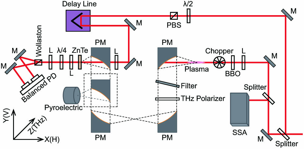
The experimental setup is sketched in Fig. 1, which allows us to generate THz by two-color plasma and characterize the polarization of the emitted THz with both a pyroelectric sensor and the electro-optic sampling (EOS) technique [35,36]. A chirped-pulse-amplification (CPA) laser system (Coherent Legend) delivers laser pulses with a central wavelength at 800 nm, a transform-limited pulse width of 50 fs, and maximum energy of 7 mJ. The variation of the laser chirp is achieved by changing the distance between the two gratings of the pulse compression unit in the CPA laser system. The beam from the laser output is split into two parts by a plate beam splitter. The reflected part is used as a probe to measure the THz electric field with EOS, while the transmitted part is used as a pump to generate two-color plasma for THz emission. In the probe arm, the intensity can be tuned by a composition of a half-wave plate and a polarizing beam splitter (PBS). Two mirrors mounted on a delay line change the time delay between THz and the EOS probe pulse. In the pump arm, a beam splitter is inserted to reflect a portion of the beam toward a single-shot autocorrelator (SSA, Coherent) used to monitor the laser pulse width. The transmitted pulse of is focused by a plano–convex lens with 300 mm focal length. Between the lens and its focus, a 100-μm-thick type-I -BBO crystal is inserted to generate SH. The BBO is mounted on a stage to change the BFD. The angle between the extraordinary axis of the BBO and the pump laser polarization is . The FW normally impinges on the BBO crystal. Due to the birefringence of the BBO crystal, the FW becomes elliptically polarized after passing through the BBO [32]. The ellipticity of the FW is 0.64, which is defined as the ratio between the lengths of the polarization ellipse’s minor and major axes. The SH is linearly polarized along the extraordinary axis of the BBO because of the type-I phase matching.
Figure 1.Experimental setup. The beam from the laser is split into two parts. The reflected part is used as a probe to detect THz with electro-optic sampling (EOS), and the other is used as a pump to generate THz. In the pump arm, another beam splitter is inserted to reflect part of the beam for monitoring the pulse width with SSA. The pump laser is focused by a lens. Between the lens and its focus, a BBO crystal is inserted. Transmitted FW and SH create two-color plasma, and THz is radiated. A PM collimates THz, and a second PM focuses THz. A third PM collimates THz again, and a fourth PM focuses THz for EOS. Between the third and fourth PMs, another PM mounted on a flip platform (PM in the dashed square) switches between THz electric field and power detections. The inset coordinate system shows the THz polarization and propagation directions. M, mirror; L, lens; PM, parabolic mirror; PD, photodiode; PBS, polarizing beam splitter; SSA, single shot autocorrelator.
An off-axis parabolic mirror (PM) with a reflected focal length of 4 in. (1 in. = 2.54 cm) collimates the THz beam from the two-color plasma. A silicon wafer is adopted to reflect away the residual laser beam. A Teflon plate is applied to attenuate the mid-infrared light generated by the plasma, transmitting only the THz wave. A second 4 in. PM focuses the THz beam, and a third 4 in. PM collimates it. Finally, a fourth hole-drilled 2 in. PM focuses the THz beam onto the EOS crystal. In the collimated THz beam between the third and fourth PMs, another 4 in. PM is mounted on a flip platform. By rotating the platform, the PM can be placed into the THz beam to focus it into a pyroelectric sensor for THz power measurement; alternatively, the PM can be removed to allow THz electric field measurement with EOS. In this case, the EOS probe laser is focused through the hole in the fourth PM and collinearly propagates onto a 200-μm-thick (110)-cut ZnTe crystal with the THz beam focused by the fourth PM. Then, the EOS probe is collimated by a lens and transmitted through a quarter-wave plate, after which it is focused by another lens and split by a Wollaston prism. The two beams from the Wollaston prism arrive on a balanced photodiode, and an electronic system measures the intensity difference between these two beams.
B. Polarization Characterization
Two methods are employed to measure the polarization of the THz radiation. In the first one, we measure the THz power transmitted through a polarizer with a pyroelectric sensor. The polarization state is obtained by measuring the THz power versus the orientation angle of the polarizer. An elliptically polarized electromagnetic wave can be decomposed into two orthogonal linearly polarized waves. These two waves can be expressed as and , with , , and , respectively, denoting angular frequency, wavenumber, and phase difference between and ; and are the constant parameters indicating the strength of the waves. The average power of the elliptically polarized electromagnetic wave passing through a polarizer whose transmission axis angle is with respect to axis can be obtained by projecting and on the transmission axis of the polarizer,
The other method concerns measuring the electric field of the two orthogonal waves with the EOS. Herein, we measure the horizontal (vertical) THz component, which is parallel (normal) to the experimental table and normal to the THz propagation direction. To measure the horizontal and vertical components, we rotate the ZnTe crystal while keeping the EOS probe polarization horizontal. When (001) direction is vertical (horizontal), only the horizontal (vertical) component of THz is detected [35,36].
Both methodologies are employed to validate the polarization state of the THz radiation for each measurement. As an example, we show in Fig. 2 the polarization characterization for the case of negatively chirped FW with a pulse width of 60 fs and BFD of 65 mm, which is roughly the position where maximum THz is generated. Figure 2(a) shows THz power versus transmission axis angle of the THz polarizer. Red open circles are experimental data, and the black curve is the fit with Eq. (1). Figure 2(b) plots the time-dependent electric fields of horizontal (blue) and vertical (red) components. The three-dimensional electric field (black) and the projected polarization trajectory (violet) are also drawn in Fig. 2(b). The projected polarization trajectory indicates that the THz is elliptically polarized. Previous investigation suggests that the cross-phase modulation of the SH induced by the FW leads to the THz polarization ellipticity [32]. The orientations of the polar plot of the THz power versus THz polarizer orientation angle and the projected polarization trajectory of the electric field are consistent. For simplicity, in the following, only the polarization trajectory of the electric field measured by EOS is shown. Nevertheless, the THz power versus the polarizer orientation angle was also measured to validate the EOS measurements.
Figure 2.THz polarization characterized by a pyroelectric sensor and electro-optic sampling (EOS). (a) Power of THz transmitted through a THz polarizer versus the transmission axis angle of the THz polarizer with respect to axis. The power of THz is measured with a pyroelectric sensor. Red open circles denote experimental data, and the black curve is fit with Eq. (1). (b) Time-dependent horizontal (blue) and vertical (red) THz electric field with the three-dimensional (black) electric field and projected polarization trajectory (violet). THz electric field is measured with EOS.
A. Effect of Laser Chirp on THz Polarization at Fixed BBO-to-Focus Distance
The effect of the laser chirp on the THz polarization is investigated at . The THz polarization trajectories with positive and negative chirps are depicted in Fig. 3. As shown in Fig. 3(a), the THz polarization trajectory rotates clockwise with increasing pulse width when the laser is positively chirped. In stark contrast, the THz polarization trajectory first rotates clockwise for negatively chirped pulses when the pulse width increases from 53 to 78 fs as shown in Fig. 3(b). Then, the polarization trajectory rotates anticlockwise for the pulse width increasing from 78 to 315 fs as shown in Fig. 3(c). Several investigations revealed that the phase difference between FW and SH () plays a vital role in THz polarization [14,28–31]. Chirp-induced change of pulse overlap was proposed to account for the variation of THz yield versus laser chirp [23]. We assume that the laser chirp can also induce the phase difference between FW and SH, leading to the THz polarization’s rotation. The following subsection will describe how the laser chirp results in the phase difference between FW and SH.
Figure 3.THz polarization variation with positive and negative chirps. The black arrows show the THz polarization rotation by looking into the increasing pulse width direction. The red arrows indicate the THz polarization rotation by looking into the increasing phase difference direction (see details in the text). The numbers near the curves are the pulse widths. (a) Polarization rotation for positively chirped pulses. (b) THz polarization rotation in the range with a negative chirp. (c) THz polarization rotation in the range with a negative chirp.
The laser chirp simultaneously affects the SH generation and the phase difference between the FW and SH. We observed that SH generation varies with the pulse duration. However, the THz polarization exhibits behavior similar to the THz polarization versus the phase difference introduced by BFD [29] and wedges [28]. The BFD also simultaneously changes the SH generation and the phase difference (similar to our case) [29]. In contrast, wedges only change the phase difference without changing the SH intensity [28]. However, the results for these two methods on the THz polarization versus phase difference are comparable. These results indicate that the change in phase difference rotates the THz polarization rather than the change in the SH generation.
B. Chirp-Induced Phase Difference between FW and SH
Recent investigation suggests that chirp-induced change of pulse overlap plays a crucial role in the THz yield from two-color plasma [23]. The chirp-induced change of pulse overlap may also result in the phase difference between the FW and SH. Herein, we experimentally investigate how the laser chirp affects the phase difference. To demonstrate chirp-induced phase difference, we measured the THz yield versus BFD for different chirps to extract the initial phase difference () between FW and SH at BFD equal to 65 mm. The phase difference between FW and SH can be altered by changing BFD because of the air dispersion [29]. The phase difference between FW and SH versus BFD [14,23] is where is the velocity of light in vacuum; and are, respectively, the refractive indices of SH and FW in the air; and , respectively, denote the angular frequencies of SH and FW; and denotes the BFD difference compared with the starting point of . The photocurrent model [14] predicts that the THz electric field versus obeys the behavior of . We experimentally measured the THz intensity versus BFD with a pyroelectric sensor and fitted the data with the following formula: where , A, B, C, and are constants to be determined by fitting experimental data with Eq. (3). The linear part in Eq. (3) denotes the nonoscillatory background, which may result from other mechanisms such as bremsstrahlung from electron–atom collisions [24,37]. The experimental and fitting data are plotted in Fig. 4. The error bars in Fig. 4 represent statistical errors at a confidence level of 95%, which is also the same as the error bars in the other figures.
Figure 4.THz intensity versus BBO-to-focus distance (BFD) with different laser chirps. The movement direction of the curves with pulse width is related to the initial phase difference (chirp-induced phase) between FW and SH. The dashed lines highlight the movement directions of the curves. Open circles and solid lines, respectively, indicate experimental and fitting results. The plots are vertically shifted for clarity. (a) THz intensity versus BFD when the laser is positively chirped. Curves constantly shift left with increasing pulse width from 50 to 445 fs. (b) THz intensity versus BFD when the laser is negatively chirped. The curves first move right when the pulse width increases from 50 to 80 fs and then shift left when the pulse width increases from 80 to 365 fs.
In Fig. 4(a), we show that, for positively chirped pulses, the curves shift left with increasing pulse width. The black segmented line connecting the maxima of the curves highlights this trend. On the contrary, the curves shift right when the pulse width increases from 50 to 80 fs for negatively chirped pulses, as shown in Fig. 4(b). Then, the curves shift left with a further increment of the pulse width. The shift between the curves depends on the initial phase difference .
Figure 5(a) plots the initial phase difference extracted from Fig. 4, which elucidates how the chirp affects the phase difference between the FW and SH. Figure 5(b) plots THz yield versus laser chirp at the same , which is in perfect agreement with the simulation and experimental results in Ref. [23]. The extracted initial phases in Fig. 5(a) are the phase differences at the same . Thus, the phase difference resulting from the air dispersion is the same for all different laser chirps, while the rest of the phase difference of can be assigned to the chirp-induced phase difference. Figure 5(a) shows that the chirp-induced phase is asymmetric regarding the transform-limited pulse width of 50 fs, which may result from the different strength of self-compression for the positive and negative chirps [23]. As shown in Fig. 5(a), first decreases and then increases with increasing pulse width for the negative chirp. reaches a minimum at pulse width around 80 fs with a negative chirp. On the contrary, the initial phase difference always increases with increasing pulse width when the laser pulse is positively chirped. The minimum at pulse width around 80 fs with negative chirp reflects the sudden change of phase shift direction shown in Fig. 4(b). The minimum may result from the very strong self-compression of the pulse due to the plasma when the pulse is slightly negatively chirped [23].
Figure 5.Initial phase difference (chirp-induced phase) and THz yield versus laser chirp. (a) Initial phase difference extracted by fitting the measured THz yield versus BBO-to-focus distance (BFD) with Eq. (3) as shown in Fig. 4. always increases with pulse width when the laser is positively chirped, whereas first decreases to a minimum and then increases with pulse width when the laser is negatively chirped. (b) THz yield versus laser chirp measured at BFD equal to 65 mm.
It can also be observed that the dip of the phase difference presented in Fig. 5(a) coincides with the dip of THz yield presented in Fig. 5(b) around pulse width of 80 fs with a negative chirp. In Ref. [23], the authors assumed that the chirp-induced change of pulse overlap leads to the variation of THz yield versus laser chirp. The coincidence of the two dips presented in Fig. 5 suggests that the laser-induced chirp may also play a crucial role in the THz yield. It should be pointed out that, although the change of pulse overlap can result in phase difference, different pulse overlaps can possess the same phase difference, as shown in Ref. [23]. In this sense, it seems that both the laser-induced phase difference and overlap difference are crucial for THz generation.
C. THz Polarization Rotation versus Chirp-Induced Phase Difference between FW and SH
Now we correlate the chirp-induced phase difference between FW and SH with the THz polarization rotation. The THz polarization rotates clockwise for the positive chirp with an increasing pulse width, as shown in Fig. 3(a). At the same time, the initial phase difference between FW and SH increases with an increasing pulse width, as shown in Fig. 5(a). Thus, the THz polarization rotates clockwise with an increasing phase difference between FW and SH for the positive chirp.
For negatively chirped pulses, we discuss two cases corresponding to two different pulse width ranges. Looking into the increasing pulse width direction, one observes that the THz polarization rotates clockwise with increasing pulse width in the range of , as shown in Fig. 3(b). The initial phase difference between FW and SH decreases with the increasing pulse width in the same range as shown in Fig. 5(a). Therefore, looking into the increasing initial phase difference (from to 50 fs), one observes that the THz polarization rotates anticlockwise with an increasing initial phase difference in the range of 50–80 fs.
In the pulse width range of , one observes that the THz polarization rotates anticlockwise with increasing pulse width by looking into the increasing pulse width direction, as shown in Fig. 3(c). The initial phase difference between FW and SH increases with increasing pulse width, as shown in Fig. 5(a). Hence, the THz polarization also rotates anticlockwise with an increasing phase difference between FW and SH in this range.
The THz polarization rotates clockwise and anticlockwise with increasing pulse width in the ranges of and by looking into the increasing pulse width direction. However, one observes that the THz polarization rotates anticlockwise with the increasing initial phase difference by looking into the increasing initial phase difference in both ranges.
D. Effect of the BBO-to-Focus Distance on THz Polarization for Different Chirp Configurations
The above subsection concludes that the THz polarization rotates clockwise with increasing phase difference when the laser is positively chirped. In contrast, the THz polarization rotates anticlockwise with an increasing phase difference between FW and SH for a negative chirp. We investigate how THz polarization changes versus the phase difference between FW and SH at fixed laser chirps to verify this conclusion further. To perform this measurement, the phase difference between FW and SH at a fixed laser chirp is varied by changing the BFD [29]. The results at pulse width equal to 110 fs with positive chirp and 340 fs with negative chirp are shown in Fig. 6. The THz polarization trajectories are obtained in the range of the BFD from 65 to 105 mm with an increment of 5 mm. The phase difference () between FW and SH at each BFD is extracted by fitting the experimental THz intensity versus BFD with Eq. (3) [see Figs. 6(b) and 6(d)]. Figures 6(a) and 6(c) plot THz polarization trajectories with different phase differences between FW and SH.
Figure 6.THz polarization versus BBO-to-focus distance (BFD) at fixed laser chirps. The phase difference variation between FW and SH is realized by changing BFD for two typical positive and negative laser chirps. The left (right) column shows THz polarization trajectories and THz yield for pulse width equal to 110 (340) fs with a positive (negative) chirp. (a) and (c) THz polarization trajectories rotate clockwise (anticlockwise) with an increasing phase difference between FW and SH when the laser is positively (negatively) chirped. The arrows show the rotation directions. (b) and (d) THz yield versus BFD. The red open circles are experimental data. The black curves are fitting results with Eq. (3). The initial phase difference between FW and SH is obtained by fitting. Then the phase difference between FW and SH at each BFD is calculated with Eq. (2).
From the data reported in Figs. 6(a) and 6(c), we notice the same behaviors described in the above subsection. Indeed, Fig. 6(a) shows that THz polarization trajectory rotates clockwise with an increasing phase difference between FW and SH for a positive chirp, while Fig. 6(c) reveals that THz polarization trajectory rotates anticlockwise with increasing phase difference for a negative chirp.
Figures 3–5 show that laser chirp can induce the phase difference as the other methods, such as BFD and wedges. The chirp-induced phase difference leads to the variation of THz polarization. The chirp-induced phase may result from the variation of pulse overlap in the plasma as recently demonstrated by simulation [23]. The different phase between the FW and SH results in different electronic trajectories, as shown by simulation [28], which results in different THz polarization. Furthermore, Figs. 3–5 present that the THz polarization rotates clockwise and anticlockwise with increasing chirp-induced phase difference between the FW and SH for positive and negative chirps. In Fig. 6, the phase difference between the FW and SH is varied with BFD. Figure 6 also shows that THz polarization rotates clockwise and anticlockwise with increasing phase difference for positively and negatively chirped pumps. The results presented in Figs. 3–6 are in good agreement.
4. CONCLUSION
In summary, we investigated the impact of laser chirp on the polarization of THz from two-color plasma. At fixed BFD, chirp-induced phase difference results in the variation of the THz polarization versus chirp. Detailed inspection reveals that the positive and negative chirps have opposite impacts on the THz polarization. The THz polarization rotates clockwise with an increasing phase difference between FW and SH when the laser is positively chirped. On the contrary, the THz polarization rotates anticlockwise with an increasing phase difference between FW and SH when the laser is negatively chirped. Compared with the THz polarization versus the chirp-induced phase difference, the chirp-induced phase difference versus the pulse width of the laser is more complicated. For the positive chirp, the phase difference monotonically increases with the increasing pulse width of the laser. In contrast, for negatively chirped pulses, the phase difference first decreases and then increases with the increasing pulse width. The opposite effects of positive and negative chirps on THz polarization are further confirmed by investigating the dependence of THz polarization on BFD at fixed laser chirps. These discoveries may apply to controlling the THz radiation polarization from two-color plasma. They can also provide clues to understand the microscopic physical mechanism resulting in THz generation.
Sen Mou, Luca Tomarchio, Annalisa D’Arco, Marta Di Fabrizio, Salvatore Macis, Alessandro Curcio, Luigi Palumbo, Stefano Lupi, Massimo Petrarca, "Impact of laser chirp on the polarization of terahertz from two-color plasma," Photonics Res. 11, 978 (2023)