• Chinese Optics Letters
  • Vol. 21, Issue 4, 041205 (2023)
Jiabin Wang1, Xinzhe Zeng1, Jian Zhou1, Jiayu Hao1, Xingyu Yang1, Yue Liu1, Wenhuan Chen1, Song Li1, Yunxiang Yan1、2, Tao Geng1、*, Weimin Sun1, and Libo Yuan3
Author Affiliations
  • 1Key Laboratory of In-fiber Integrated Optics, Ministry of Education, Harbin Engineering University, Harbin 150001, China
  • 2Qingdao Innovation and Development Center of Harbin Engineering University, Qingdao 266000, China
  • 3Photonics Research Center, School of Electronic Engineering and Automation, Guilin University of Electronic Technology, Guilin 541004, China
  • show less
    DOI: 10.3788/COL202321.041205 Cite this Article Set citation alerts
    Jiabin Wang, Xinzhe Zeng, Jian Zhou, Jiayu Hao, Xingyu Yang, Yue Liu, Wenhuan Chen, Song Li, Yunxiang Yan, Tao Geng, Weimin Sun, Libo Yuan. Highly sensitive torsion sensor based on Mach–Zehnder interference in helical seven-core fiber taper[J]. Chinese Optics Letters, 2023, 21(4): 041205 Copy Citation Text show less

    Abstract

    We propose a high-sensitivity bidirectional torsion sensor using a helical seven-core fiber taper embedded in multimode fiber (MHSTM). Sensors with different taper waists and helical pitches are fabricated, and their transmission spectra are obtained and analyzed. The waist and length of the sandwiched seven-core fiber are finally determined to be 68 µm and 3 mm, respectively. The experimental results show that the clockwise and counterclockwise torsion sensitivities of the proposed sensor are 2.253 nm/(rad/m) and -1.123 nm/(rad/m), respectively. When tapered waist diameter reduces to 48 µm, a superior torsion sensitivity of 5.391 nm/(rad/m) in the range of 0–4.24 nm/(rad/m) is obtained, which is 46 times as large as the traditional helical seven-core fiber structure. In addition, the MHSTM structure is also relatively stable to temperature variations.

    1. Introduction

    In recent years, torsion sensors have been extensively studied and developed due to the increasing demand for structural health monitoring. So far, various torsion sensors have been reported, including mechanical, electromagnetic, and all-fiber types. Among them, fiber-optic sensors have attracted wide attention due to their excellent characteristics, such as compact size, high sensitivity, strong immunity to electromagnetic interference, corrosion resistance, and compatibility with fiber-optic systems. However, ordinary fibers are almost insensitive to torsion due to their symmetrical structure. Therefore, special fibers such as polarization-maintaining fibers (PMFs)[1], photonic crystal fibers (PCFs)[2,3], and multicore fibers (MCFs)[46] are widely used for torsion measurements. Liu et al. fabricated a torsion sensor using a seven-core fiber (SCF) with a torsion sensitivity of 0.4 nm/(rad/m)[4]. The cylindrically symmetric fiber sensors have similar responses to clockwise (CW) and counterclockwise (CCW) twists.

    To achieve direction recognition, efforts have been devoted to three main processes. One is to apply the asymmetric destructive processes on optical fibers using a femtosecond laser or CO2 laser. The main drawbacks of these methods are low mechanical strength and high cost. Another method is to achieve asymmetric structure by eccentric fusion-splicing fiber[7]. The third is to fabricate the helical structure (HS). When a helical fiber structure is twisted, the helical pitch of the HS changes accordingly. Thus, the torsion sensors based on HS structure not only exhibit high sensitivity but also have the ability of direction judgment. Ulrich and Simon mechanically twisted the single-mode fiber (SMF) to generate circular birefringence for the first time[8]. After that, torsion sensors based on HS structure fabricated by hydrogen–oxygen flame[9], CO2 laser[10], arc discharge, and laser-heated sapphire transistor[11] have been reported. Low-torsion sensitivity still limits the development of fiber torsion sensors nevertheless. Therefore, easily fabricated directional torsion sensors with high mechanical strength and high sensitivity are expected.

    In this Letter, we present a directional torsion sensor composed of a sandwiched helical SCF taper (MHSTM). The MHSTM structure is fabricated by a homemade fiber fusion tapering and rotating platform supported by a graphite heating unit. By tapering the SCF, the photoelastic effect in the cladding is enhanced when torsion is applied to the sensor. Thus high sensitivity and the ability to distinguish torsion directions are obtained. The torsion sensitivities of the proposed sensor in CW and CCW directions are 2.253 and 1.123nm/(rad/m), respectively. When the taper waist is decreased to 48 µm, a maximum torsion sensitivity of 5.391 nm/(rad/m) is obtained. Compared with other helical SCF-based sensors, the maximum torsion sensitivity we obtained is improved by 46 times.

    2. Fabrication and Principle

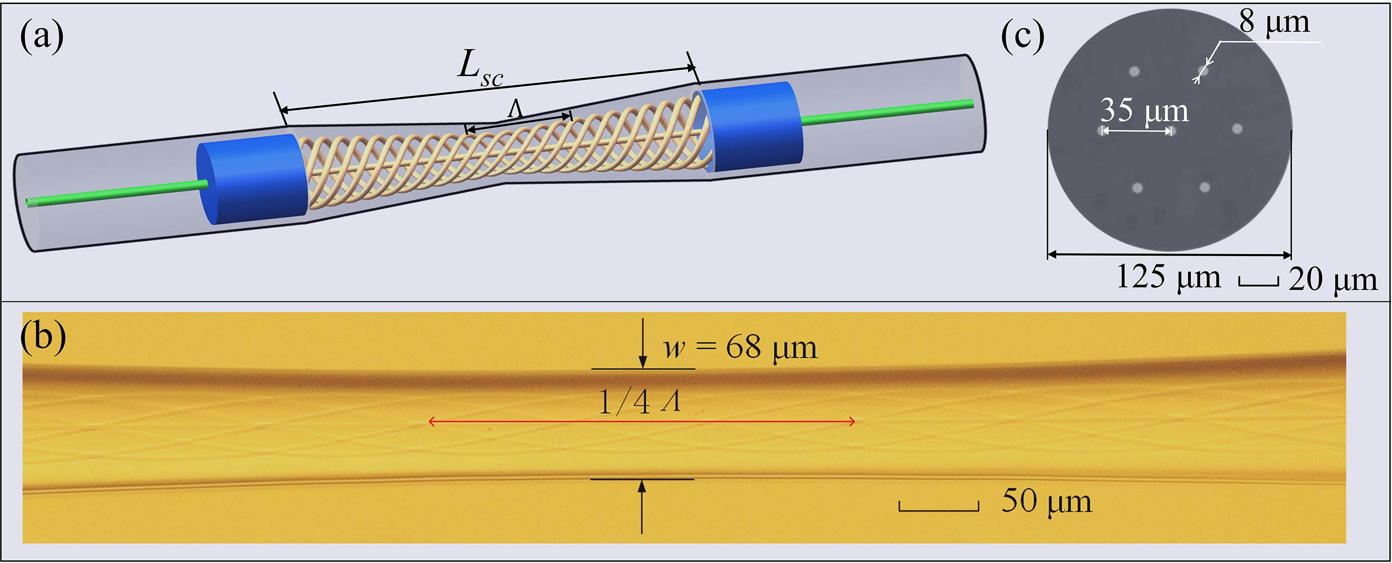
    The schematic diagram of the MHSTM structure is displayed in Fig. 1(a). The lead-in and lead-out fibers are all SMFs (SMF-28e+, Corning). The core and cladding diameters of the multimode fiber (MMF) (YOFC Co., Ltd.) are 105 and 125 µm, respectively. The SCF used is the commercially available product (SM-7C1500, Fibercore). The cross section of the SCF is shown in Fig. 1(c). The SCF has a central core and six satellite cores, where all the cores have identical diameters d of 8 µm and core distances of 35 µm. The cladding diameter is 125 µm.

    (a) Schematic diagram of the MHSTM structure; (b) micrograph of the MHSTM structure under phase contrast microscope; (c) cross-sectional micrograph of the SCF.

    Figure 1.(a) Schematic diagram of the MHSTM structure; (b) micrograph of the MHSTM structure under phase contrast microscope; (c) cross-sectional micrograph of the SCF.

    There are two steps to fabricate an MHSTM structure. First, we spliced the SCF between two segments of MMFs by a fiber cleaver (FC-6S, Sumitomo) and a fusion splicer (FSM-62C, Fujikura). The length of the MMF and SCF is 0.5 mm and 3 mm, respectively. Second, we fix the structure on the helically tapered device, which consists of one rotating motor and two translation stages (Fig. 2). An “Ω” shaped heating unit is applied to melt the silica fiber. The temperature of the fusion area is controlled by adjusting the input power of the heating unit. A well-designed program is written into the controller to realize the simultaneous heating, tapering, and rotating of the fiber. Finally, we fabricate samples with desired helical pitch, taper waist, and length by setting the speed and time of the horizontal and rotational motors in the program.

    Configuration of the homemade fiber fusion tapering and rotating platform.

    Figure 2.Configuration of the homemade fiber fusion tapering and rotating platform.

    As shown in Fig. 1(b), only the six outer cores are helical, while the center core stays straight. When fiber is rotated, according to the optic-elastic effect, the effective refractive index (ERI) increases, which is expressed as n(α)=n0[1+r2(α±α0)2/2],where n0 represents the mode ERI under the untwisted state, r refers to the radius away from the fiber center, α and α0 are the permanent and temporary torsion rate, respectively, and “+” and “−” denote the consistent and opposite direction[5]. Thus, the effective optical path lengths and ERIs of the outer core modes (OCMs) and cladding modes (CMs) change with the applied torsion, while those of the center core mode (CCM) keep almost unchanged[3]. When the light propagates to the SCF from the input MMF, a part of the light couples into the seven cores, and the rest enters into the cladding. When light propagates through the helical fiber taper (HST) region, phase differences are generated as the light propagates along different paths. Then CCM, OCM, and CM finally couple back to the MMF and result in Mach–Zehnder interference (MZI). Therefore, the spectrum of the structure is mainly caused by the superposition of multiple MZIs[12]. The interference light intensity of each MZI is expressed as I=I1+I2+2I1I2cosφ,where I1 and I2 are the intensities of the two modes. Additionally, φ is the phase difference between the two modes, which is expressed as φ=2πΔneffL/λ,where Δneff refers to the difference of the ERI between the two interfered modes. L is the effective interference length. λ is the wavelength of the incident light. An interference dip emerges when φ=(2k+1)π, k=0,1,2, is established. The wavelength of the dip is determined by λ=2ΔneffL/(2k+1).

    The torsion sensitivity S of the dip is calculated by taking the partial derivatives of the torsion rate on both sides of Eq. (4). For interference dips between the CCM and OCM, the CCM and CM, the torsion sensitivity is expressed as S=λαn0Lr2α+ΔneffLα.

    For interference dips generated from CCM and CM, the torsion sensitivity is expressed as S(ncorco2nclrcl2)Lα+ΔneffLα.

    3. Experimental Results and Discussions

    As shown in Fig. 1(b), the total length LSC and waist diameter w of the helical SCF taper are 3.8 mm and 68 µm, respectively. The transmission spectrum is shown in Fig. 3(a). In order to further analyze the interference components contained in the spectrum, fast Fourier transform (FFT) is applied, as shown in Fig. 3(b). The spatial frequency is a function of Δneff, according to the theory of interference. The Δneff of CCM, OCM, and first-order CM in SCF induced by torsion can reach 103104, corresponding to the three spatial frequencies of 0.0043, 0.0099, and 0.0128nm1[5]. The other weak peaks in the FFT spectrum represent the interference between the high-order CMs.

    (a) Transmission spectrum of the MHSTM; (b) FFT spectrum of the transmission spectrum.

    Figure 3.(a) Transmission spectrum of the MHSTM; (b) FFT spectrum of the transmission spectrum.

    To measure the torsion sensitivity, the proposed sensor is connected to a supercontinuum source (SC, YSL Photonics SC-5) by the lead-in fiber. The lead-out fiber is connected to an optical spectrum analyzer (OSA, Yokogawa AQ6370D). A pair of fiber rotators (HFR-007, Thorlabs) holds the sensor, as shown in Fig. 4. One rotator is fixed, and another rotates 30° each step. The distance between the two rotators is 37.0 cm. It is worth noting that we define the CW direction as the consistent torsion direction with the HST, while the opposite direction is defined as the CCW direction.

    Experimental setup for torsion sensitivity measurement.

    Figure 4.Experimental setup for torsion sensitivity measurement.

    The spectrum evolution as the torsion rate changes from 14.15 rad/m to 9.91rad/m is shown in Fig. 5(a). We measured the torsion sensitivity of the three target dips in Fig. 3(a), and the experimental results are shown in Figs. 5(b) and 6. The central wavelength of dip A is 1542.6 nm, which is close to the typical fiber communication wavelength. Also, its torsion sensitivity is the highest among the three dips. As a result, we choose dip A for torsion measurement. It is observed from Fig. 5(b) that the sensor sensitivities are 2.253 and 1.123nm/(rad/m) in CW and CCW directions with R2 of 0.996 and 0.974, respectively. Dip A shifts toward a longer wavelength with the increased torsion rate. Based on the theoretical analysis mentioned above, the wavelength of the dip is proportional to Δneff. When the sensor is twisted CW/CCW, the torsion-induced ERI increases/decreases. Moreover, Eqs. (5) and (6) suggest that torsion sensitivity is a function of α and Δneff. Additionally, torsion is apt to concentrate in the waist region; thus, Δneff in a thinner taper further increases. This explains the high torsion sensitivity of our sensor well[13].

    (a) Changing spectrum as the torsion force is applied; (b) piecewise linear fit of dip wavelength as a function of twist rate.

    Figure 5.(a) Changing spectrum as the torsion force is applied; (b) piecewise linear fit of dip wavelength as a function of twist rate.

    Piecewise linear fitting curves of wavelength of the (a) dip B and (b) dip C to the torsion rate.

    Figure 6.Piecewise linear fitting curves of wavelength of the (a) dip B and (b) dip C to the torsion rate.

    In order to obtain the optimal sensing characteristics, we optimized the helical pitch Λ and taper waists w of the sensor. Two sets of experiments with w and Λ as single variables are performed. The three samples in the first set have a helical pitch of 540 µm and a taper waist of 48, 68, and 81 µm, respectively. The maximum torsion sensitivity of SAMPLE 1 is 5.391 nm/(rad/m) in the range of 0–4.24 rad/m. The torsion sensitivity of SAMPLE 2 is 2.253 nm/(rad/m) in the range of 0–14.15 rad/m. The torsion sensitivity of SAMPLE 3 is 0.195 nm/(rad/m) in the range of 0–14.15 rad/m. It is proved that the sensor with a thinner taper has higher sensitivity, but it also suffers from poor mechanical intensity and a limited measurement range[14]. In addition, according to Eq. (1), the sensitivity varies with α, so the linear torsion response can be obtained only when α0 is much larger than α. Figure 7(b) shows the comparison of the torsion sensitivities of the sensor with different helical pitches. The taper waist diameter of the second set is 55 µm. According to our analysis, the denser helix always results in higher sensitivities. But it can be seen from Fig. 7(b) that the torsion sensitivity is not proportional to the helical pitches Λ. The torsion sensitivities change a little, which is negligible compared to the fluctuations of the taper waist diameter. So the disproportionate trend is mainly due to the experimental error of the taper waist. Temperature stability is also a quite important characteristic in engineering applications. Our temperature sensitivity is 36 pm/°C from 30° to 100°C (seen in Fig. 8).

    Linear fits of the dip wavelength to the torsion rate. (a) Under different taper waists w; (b) under different helical pitches Λ.

    Figure 7.Linear fits of the dip wavelength to the torsion rate. (a) Under different taper waists w; (b) under different helical pitches Λ.

    (a) Transmission spectrum evolution as temperature changes; (b) linear fit of the dip wavelength as a function of temperature.

    Figure 8.(a) Transmission spectrum evolution as temperature changes; (b) linear fit of the dip wavelength as a function of temperature.

    Table 1 compares the characteristics of several sensors proposed previously and in this work. The proposed MHSTM structure exhibits distinct advantages in sensing performance. Moreover, light weight, compact size, and low fabrication cost all provide greater potential for the practical application of our structure.

    TypeBidirectional DiscriminationMax Torsion Sensitivity (nm/(rad/m))Ref.
    SCFNo0.4[4]
    Squared coreless fiberNo1.286[15]
    Tapered SCFNo1.89[16]
    Helical SCFYes−0.118[5]
    Helical PMF taperYes−3.191[2]
    MHSTMYes5.391This work

    Table 1. Comparison of Torsion Sensors

    4. Conclusion

    In conclusion, theoretical analysis and experimental demonstration of a high-sensitivity fiber torsion sensor based on MHSTM structure are presented. Our structure, fabricated by a graphite heater, is relatively low-cost compared to a CO2 laser and heated sapphire transistor. And the torsion sensitivity reaches 2.253 nm/(rad/m) (0–14.15 rad/m) and 1.123nm/(rad/m) (9.910rad/m). Furthermore, by reducing the taper waist and making the helix denser, the torsion sensitivity is further increased to 5.391 nm/(rad/m) with a waist diameter of 48 µm. In addition, the temperature response is as low as 36 pm/°C. The wavelength of the target dip only drifts 2.6 nm in the range of 30° to 100°C. The MHSTM-based sensor combines the advantages of high sensitivity, direction discrimination, light weight, and compact size, and thus has great potential in the field of practical torsion sensing, especially in bionic robots, building safety monitoring, and the automotive industry.

    References

    [1] Y. Q. Zhu, Y. S. Yu, Y. Zhao, Q. Guo, X. Y. Ming, C. X. Lei, H. B. Sun. Highly sensitive directional torsion sensor based on a helical panda fiber taper. IEEE Photon. Technol. Lett., 31, 1009(2019).

    [2] F. Zhang, S. Liu, Y. Wang, Y. J. Huang, X. Z. Xu, C. L. Fu, T. S. Wu, C. R. Liao, Y. P. Wang. Highly sensitive torsion sensor based on directional coupling in twisted photonic crystal fiber. Appl. Phys. Express, 11, 042501(2018).

    [3] P. St.J. Russell, R. Beravat, G. K. L. Wong. Helically twisted photonic crystal fibres. Philos. Trans. R. Soc. A, 375, 20150440(2017).

    [4] C. Liu, Y. J. Jiang, B. B. Du, T. Wang, D. Y. Feng, B. Q. Jiang, D. X. Yang. Strain-insensitive twist and temperature sensor based on seven-core fiber. Sens. Actuator A Phys., 290, 172(2019).

    [5] H. L. Zhang, Z. F. Wu, P. P. Shum, X. G. Shao, R. X. Wang, X. Q. Dinh, S. N. Fu, W. J. Tong, M. Tang. Directional torsion and temperature discrimination based on a multicore fiber with a helical structure. Opt. Express, 26, 544(2018).

    [6] G. L. Yin, L. Lu, L. Zhou, C. Shao, Q. J. Fu, J. D. Zhang, T. Zhu. Distributed directional torsion sensing based on an optical frequency domain reflectometer and a helical multicore fiber. Opt. Express, 28, 16140(2020).

    [7] G. L. Yin, Q. J. Fu, P. X. Yang, T. Zhu. Direction-discriminating torsion sensor based on optical fiber Mach-Zehnder interferometer. Opt. Laser Technol., 156, 108461(2022).

    [8] R. Ulrich, A. Simon. Polarization optics of twisted single-mode fibers. Appl. Opt., 18, 2241(1979).

    [9] Y. Y. Zhao, S. Liu, J. X. Luo, Y. P. Chen, C. L. Fu, C. Xiong, Y. Wang, S. Y. Jing, Z. Y. Bai, C. R. Liao, Y. P. Wang. Torsion, refractive index, and temperature sensors based on an improved helical long period fiber grating. J. Light. Technol., 38, 2504(2020).

    [10] X. B. Cao, D. D. Tian, Y. Q. Liu, L. Zhang, T. Y. Wang. Sensing characteristics of helical long-period gratings written in the double-clad fiber by CO2 laser. IEEE Sens. J., 18, 7481(2018).

    [11] P. Wang, H. P. Li. Helical long-period grating formed in a thinned fiber and its application to a refractometric sensor. Appl. Opt., 55, 1430(2016).

    [12] Y. J. Jiang, T. Wang, C. Liu, D. Y. Feng, B. Q. Jiang, D. X. Yang, J. L. Zhao. Simultaneous measurement of refractive index and temperature with high sensitivity based on a multipath fiber Mach-Zehnder interferometer. Appl. Opt., 58, 4085(2019).

    [13] S. J. Duan, X. Y. Bai, X. Y. Kang, H. Du, W. L. Liu, T. Geng, C. G. Tong, C. T. Sun, X. R. Jin, C. L. Lu, Y. X. Li, W. M. Sun, L. B. Yuan. High sensitive torsion sensor based on cascaded pre-twisted taper and multi-mode fiber sheets. IEEE Photon. Technol. Lett., 31, 1588(2019).

    [14] J. M. Hsu, C. L. Lee, H. P. Chang, W. C. Shih, C. M. Li. Highly sensitive tapered fiber Mach-Zehnder interferometer for liquid level sensing. IEEE Photon. Technol. Lett., 25, 1354(2013).

    [15] L. A. Wang, C. Y. Lin, G. W. Chern. A torsion sensor made of a corrugated long period fibre grating. Meas. Sci. Technol., 12, 793(2001).

    [16] B. B. Song, Y. P. Miao, W. Lin, H. Zhang, J. X. Wu, B. Liu. Multi-mode interferometer-based twist sensor with low temperature sensitivity employing square coreless fibers. Opt. Express, 21, 26806(2013).

    Jiabin Wang, Xinzhe Zeng, Jian Zhou, Jiayu Hao, Xingyu Yang, Yue Liu, Wenhuan Chen, Song Li, Yunxiang Yan, Tao Geng, Weimin Sun, Libo Yuan. Highly sensitive torsion sensor based on Mach–Zehnder interference in helical seven-core fiber taper[J]. Chinese Optics Letters, 2023, 21(4): 041205
    Download Citation