
Filip Grepl, Maksym Tryus, Timofej Chagovets, Daniele Margarone. Parametric amplification as a single-shot time-resolved off-harmonic probe for laser–matter interactions[J]. High Power Laser Science and Engineering, 2023, 11(4): 04000e45
- High Power Laser Science and Engineering
- Vol. 11, Issue 4, 04000e45 (2023)
Abstract
1 Introduction
Laser–plasma interaction and the subsequent ion acceleration mechanisms can be significantly affected by laser radiation preceding the main high-intensity pulse. Laser prepulses or the main pulse pedestal can ionize a target and form a plasma layer on its surface prior to the main pulse arrival[1,2]. Optical probing offers a reliable way to measure the preplasma dynamics and characterize the state of the target at the moment of main pulse interaction.
A commonly used approach relies on a single probe pulse split from the driver pulse, thus providing one preplasma snapshot related to the status of the target during the particular shot at a given time[3,4]. Measurement of the preplasma dynamics is then realized by variation of the delay between the driver and the probe pulse over multiple consecutive shots with the assumption of nearly identical interaction in each laser shot, which is not always valid due to plasma instabilities. Therefore, a large variety of multi-frame probing techniques have been investigated and reported in the literature. Most of them employ replicas of a single probe pulse with fundamental or harmonic frequencies that are separated spatially[5–7], spectrally[8] and/or by polarization states[9] in order to generate delay between several probe pulses. Nevertheless, these solutions can suffer from strong plasma self-emission at fundamental and harmonic frequencies and on-target laser scattering, which can be much stronger than the optical probe and saturate the detector, thus covering the phase information accumulated by the probe beam. In order to mitigate this effect, the central wavelength of the probe pulse (when generated from the same oscillator as the driver pulse) can be shifted to longer wavelengths by careful optical filtering (taking advantage of the broadband spectrum of the amplifier), which allows one to separate the probe pulse from harmonic frequencies prior to imaging[10]. Utilization of independent laser systems with different laser media as intrinsic off-harmonic probes has been also reported[11–13]. Nevertheless, the ultimate approach to off-harmonic probing can be represented by broadly tunable stand-alone systems based on optical parametric amplifiers (OPAs), which can generate ultrashort laser pulses covering the visible and near-infrared wavelengths[14,15]. Experimentalists can thus select the wavelength of the probe pulse suitable for a specific laser–target interaction depending on the observed effects.
However, all of these off-harmonic probes require additional efforts to precisely synchronize all laser oscillators in order to ensure a defined delay between the probe and the driver pulse. Furthermore, although off-harmonic probes efficiently limit plasma self-emission, they do not directly provide a time-delayed sequence of images related to a single laser shot. Conventional beam splitting techniques (for example, using the approaches described in the literature[5–7,9]) or advanced ultrafast imaging methods (using space, angle or spatial frequency division[16]) need to be applied to these off-harmonic probes to capture the plasma dynamics within a single shot.
Sign up for High Power Laser Science and Engineering TOC. Get the latest issue of High Power Laser Science and Engineering delivered right to you!Sign up now
An alternative approach consists of ultrafast imaging based on temporal wavelength division, which attributes different wavelengths to individually delayed probe pulses, thus providing naturally temporal resolution. These probe pulses, however, share harmonic frequencies with the broadband driver pulse because they are usually generated by chirping its fraction[17]. This is partially resolved by a combination of ultrafast wavelength-resolved imaging with optical parametric amplification imaging, when time-gated and wavelength-converted idler waves are captured with cameras[18]. A small fraction of the pulse from the femtosecond laser amplifier is stretched to several tens of ps and is directed through the transient event. As the chirped pulse propagates through, its different spectral components illuminate the observed event at the different time points, creating frames encoded in specific wavelengths. Subsequently, the stretched pulse (now carrying the time-resolved information in its spectral components) reaches the nonlinear crystal and interacts with a short intense pump pulse (usually generated at the second harmonic frequency of the original wavelength). As a result, optical parametric amplification occurs and the information carried in the signal is copied to the idler[19]. Since the pump pulse is short, it effectively interacts (spatially overlaps within the crystal) only with a narrow band of wavelengths in the long signal pulse. The pump pulse therefore acts as a gate and extracts only the information carried by this narrow band, which corresponds to a very short exposure time. When the delay of the pump pulse is changed, it interacts with different spectral components of the signal, thus creating an idler image that corresponds to a different time window. As a result, several OPA imaging stages arranged in a sequence (and pumped by time-delayed pulses) provide several time-delayed images with temporal resolution of approximately 50 fs from single-shot illumination[18]. However, when the stretched probe pulse is split off the heating pulse, keeping its fundamental frequency, the OPA imaging can also capture plasma self-emission or the on-target laser scattering signal. In addition, this approach requires a complex setup and does not allow one to select the wavelength of the probe pulses in order to adapt it to particular experimental conditions.
Therefore, this contribution introduces a relevant modification that combines the temporal wavelength division of ultrafast imaging with off-harmonic properties of the optical parametric amplification in order to efficiently probe high-power laser–matter interactions when prepulses or the laser pedestal ionizes the target just before the main pulse arrives. This method, based on a single OPA, can control the central wavelengths of probe pulses with mechanical delay lines in a compact setup, which allows for their simple synchronization with the high-intensity driver pulse.
2
Figure 1(a) shows the optical setup used for the generation of time-delayed off-harmonic probe pulses based on noncollinear optical parametric amplification (NOPA)[20]. The setup is based on a commercial 1 kHz Ti:sapphire laser system generating pulses at
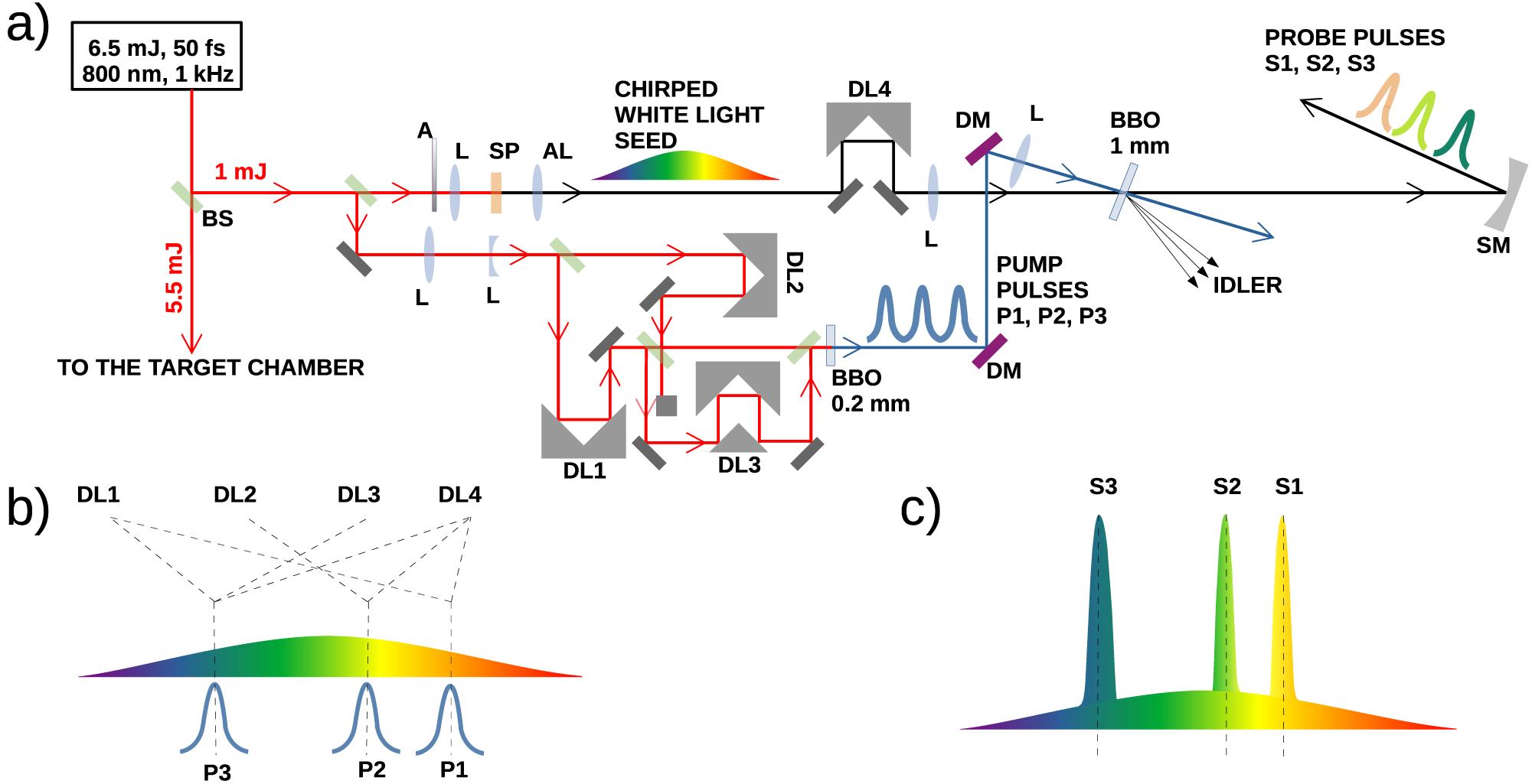
Figure 1.(a) Experimental scheme for generating three collinearly propagating time-delayed probe pulses, based on NOPA. BS, beamsplitter; L, lens; A, attenuator; AL, achromatic lens; SP, sapphire window; DL, delay line; DM, dichroic mirror; SM, spherical mirror. (b) Schematic representation of the temporal overlap of the WLC with the pump pulses in a single-stage BBO: the description schematically shows which pump pulses are controlled by specific delay lines. P1–P3, pump pulses. (c) WLC after narrowband amplification. S1–S3, probe pulses.
The central wavelengths and delays of the probe pulses are conveniently controlled by delay lines and do not require additional electronic synchronization, since the seed and pumps are initially split off the main heating beam. The wavelength of the first probe pulse S1 can be arbitrarily selected within the NOPA bandwidth. In the case of a positively chirped WLC and regarding the fact that S2 is generated to arrive later than S1, the central wavelength of S2 can only be shorter than the value assigned to S1. The shorter the wavelength of S2, the longer the time delay introduced between S1 and S2, unless the WLC is even more stretched in order to increase the delay between specific spectral components. The impacts of this operation on the bandwidth of the generated probe pulses will be discussed later. The same characteristics are then valid for probe pulse S3 with respect to the parameters of S2 and possibly for any other probe pulse. The first experimental characterization has been performed with a setup that utilizes the natural positive chirp of the WLC generated due to the normal dispersion of optics, but the order of wavelengths can be generally changed by implementation of a dispersion controlling device to increase the range of available delays for pulses with defined carrier wavelengths.
Having the chirp of the WLC seed set, the central wavelengths of the individual probe pulses (and thus the delay between them) were selected according to the availability of dichroic beamsplitters (BSs) and bandpass filters (BPFs), which were later used to spatially separate the pulses for detection. Figure 2 shows the spectral properties of all three probe pulses. Each pulse was recorded separately in order to avoid spectral interference and each measurement was normalized to 1. The central wavelengths are
![]()
Figure 2.Normalized spectra of probe pulses S1, S2 and S3. Cut-on wavelengths of the dichroic BS used for spatial separation of the pulses are shown as vertical lines. The dashed curves show the transmission function of the BPF in front of the cameras.
The delays between the central wavelengths of the probe pulses were estimated by a motion of DL4, which originally served for matching the beam path lengths of NOPA during alignment, while using only one pump pulse P1 for amplification. The results of the measurement are reported in Figure 3. The measured data were fit by a hyperbola in order to find the relationship between the wavelength and the delay of the three generated probe pulses. The goodness of fit was evaluated by the R-squared value, which is equal to 0.99. The total error of the measurement and the fit function were estimated by a 95% prediction interval, also shown in the figure. The maximum deviation of these bounds from measured values did not exceed 58 fs, which can be considered as the error bar of the performed measurement. The instrumental error, given by the duration of the pump pulse (50 fs), fits within the prediction interval. Defining the delay of probe pulse S2 as
The described setup used only one broadband NOPA stage, which is seeded and pumped by fractions of the original heating beam, and generated three time-delayed collinearly propagating pulses with different central wavelengths, which can be directly used for probing of the laser–matter interaction.
3 Experimental results
To test the performance of the described probing technique, the heating beam was attenuated and focused by a 150 mm focal length lens into the air. The created plasma channel was then probed by pulses S1, S2 and S3 with fixed delays (see Figure 3) in order to retrieve interferograms of the interaction. Overall synchronization of the driver and probe pulses was achieved by an additional delay line, which varied the arrival time of the driver pulse with a step size of
![]()
Figure 3.Measured group delay of the WLC, centered to probe pulse S2. The error bars correspond to the measured delay of central wavelengths related to the probing pulse. A 95% prediction interval estimates the total error of measurement. The respective delays between the center wavelengths of the three generated probe pulses are also shown.
A sequence of resulting pictures for two different delays of the driver beam with respect to the probes is shown in Figure 4. The microscope objective position during this measurement was slightly adjusted to make the channel visible in the raw images. Three subpictures of the plasma channel at three different time points were captured in every shot. The top subpicture corresponds to probe S1 with wavelength of
![]()
Figure 4.Plasma channel captured at two different delays of the driver beam with respect to the probe operating at the wavelength of 560 nm. Each picture corresponds to one shot and shows the plasma channel at three different times. The top subpicture corresponds to probe S1, the middle subpicture shows the plasma channel recorded by probe S2 and the bottom subpicture corresponds to the channel recorded by probe S3. The solid cyan line marks the middle of the frame and the dashed magenta line indicates the end of the developed channel captured at a specific time point.
Generally, the imaging setup can be adjusted by the motion of the microscope objective in order to enhance either the visibility of the channel (as seen in Figure 4) or the interference fringes bending. Figure 5 shows the latter case for the slightly decreased driver energy, which is advantageous for easier processing of the interference pattern by Fourier transform[23]. The result clearly shows that the phase change in each subpicture was accumulated only within the part of the frame corresponding to the specific delay of the particular probe. The global delay of this sequence was set to
![]()
Figure 5.(a) Plasma channel captured at the global delay of +0.1 ps at three different times, where the delay between probes follows the definition introduced in
4 Discussion
The overall limit of temporal resolution of the presented method (the time from one frame to another) is generally given by the overlap of the respective pulse bandwidths. The NOPA bandwidth predominantly depends on the signal-idler group velocity mismatch (GVM) as it has been widely described (also for the specific setup of the presented NOPA) in the literature[20]. Assuming that the BBO crystal in the presented method is geometrically tuned for the broadest amplification bandwidth possible with respect to the pump and seed beams, the resulting bandwidth in this work is dominantly affected by the intentionally introduced mismatch between the pump and the seed pulse durations. The mismatch limits the temporal overlap of the pulses within the nonlinear crystal because the pump acts as a gate that amplifies only a part of the WLC seed. As the pump enters the crystal, it locally overlaps with a certain portion of the stretched seed bandwidth and these spectral components are amplified. Nevertheless, the pump is generally slower than the signal for all wavelengths above 450 nm for type I NOPA in BBO crystals[24]. This phenomenon is quantified by the pump-signal GVM, which shows how much the particular spectral component of the seed foreruns the pump beam on the 1 mm path length[25]. In order to estimate the influence of this effect on the bandwidth, the pump-signal GVM for wavelengths and geometry of the assembled NOPA was considered and compared to the GD of a particular spectral component within the WLC. The GD of an ideal Gaussian pulse with a positive linear chirp based on purely quadratic temporal phase was used in calculations. All the spectral components that have relative GD with respect to the trailing edge of the pump pulse smaller than the respective GVM can reach a sufficient pump pulse intensity before they exit the crystal and thus become amplified.
Figure 6 shows the results of calculation applied on the presented NOPA. The amplification bandwidth is calculated for the central wavelength ranging from 480 to 650 nm with the seed FWHM duration equal to 1.95 ps and the pump FWHM duration equal to 50 fs in a 1 mm thick BBO crystal. The central wavelength of the seed was set to 560 nm and the bandwidth to 220 nm. All the spectral components that reached pump beam intensity above 1% of the maximum value have been considered as amplified. The calculated bandwidth is shown together with the FWHM values of the measured probe pulses (S1, S2 and S3) reported in Figure 3. The error bars correspond to the standard deviation of the FWHM from statistical processing of 15 signal acquisitions. Although the calculation uses the assumption of a purely linearly chirped seed, it shows good agreement with the measured values. The expected values of the amplification bandwidths for two additional pump pulse durations (30 and 70 fs) are shown for comparison. The top x-axis in Figure 6 determines the delay of probe pulses (when the GD of the WLC is fixed) for the specific wavelength. Since the relationship between the delay and the central wavelength is not linear, the ticks on the second x-axis are not distributed equidistantly.
![]()
Figure 6.Calculated amplification bandwidth of a probe pulse with the central wavelength ranging from 480 to 650 nm. The seed FWHM duration is equal to 1.95 ps and the pump FWHM duration is equal to 50 fs in a 1 mm thick BBO crystal. The measured values refer to the probes shown in
In order to demonstrate the effect of the seed and pump durations on the amplification bandwidth simultaneously, Figure 7 shows the calculated values for different combinations of the positively chirped seed and pump pulse lengths in a 1 mm thick BBO crystal. Both the WLC and the signal are centered at 560 nm. The widest bandwidth of the NOPA pulse is naturally achieved for the shortest seed and longest pump because of the larger overlap of spectral components in time.
Taking into account the measured bandwidths presented in Figure 2, the temporal resolution of the reported NOPA (between pulses S1 and S2) reached the limit due to the shift of probe S1 as close as possible to probe S2 (while keeping its central wavelength within the bandpass window of the equipped filter). As mentioned before, it is the GD corresponding to the particular central wavelength that determines the delay of one probe to another. As can be seen, the longer wavelengths of probe pulse S2 are reaching the bandpass window initially assigned to probe pulse S1. This configuration was still able to reliably resolve probe pulse S1 from S2 since the dynamic range of the CCD does not capture a weak S2 signal compared to a strong S1 pulse. Shifting the central wavelength of S2 closer to 570 nm caused acquisition of both pulses by one camera. The same effect occurred when a BPF for
Besides the time delay between consecutive pulses, the duration of the probe pulse itself is another important parameter that determines the temporal resolution. Generally, the illumination pulse needs to be shorter than the rapidity of the transient event. In order to estimate the time duration of the probe pulses generated by narrowband NOPA, a small fraction of the driver pulse with known duration and without any frequency conversion was set as a probe and interferograms of the same plasma channel were recorded. These interferograms were then compared to those recorded with NOPA probes operating at 530, 560 and 575 nm, respectively. It was verified that the plasma channel was extended by
Generally, the approach to maximizing the temporal resolution of the method consists of finding the probe pulse bandwidth in the dependence on the pump pulse duration and the chirp of the WLC. The shortest pump pulse duration is usually fixed and determined by the parameters of a particular laser system. As soon as the GD of the WLC is measured and its duration is therefore estimated (over the calculated range of wavelengths), Figure 7 provides the bandwidth of the probe pulse centered at 560 nm for a given length of the pump pulse. The GD of the WLC together with this value then estimates possible central wavelengths and delays of other probe pulses (one with the shorter center wavelength and the other with the longer one) because the pulse bandwidths must not overlap. The delay of the probe pulse with the shorter center wavelength can be directly calculated using the value from Figure 7 because its bandwidth will be narrower. On the other hand, some margins need to be taken into account for the probe pulse with the longer center wavelength since its bandwidth will be slightly wider (see Figure 6). These estimations are however valid for the presented NOPA based on a BBO crystal with a specific thickness. Setups with different parameters must be evaluated independently.
![]()
Figure 7.Calculated amplification bandwidth for a range of the pump pulse lengths between 30 and 120 fs and the chirped WLC pulse length between 1.5 and 2.5 ps (the values refer to the FWHM durations). The central wavelength of the amplified signal was set to 560 nm.
5 Conclusion
We have experimentally demonstrated that optical parametric amplification of narrow spectral bands of chirped white light can be successfully utilized for time- and frequency-resolved off-harmonic probing of laser-generated plasma in a single shot. This approach offers several simultaneous advantages compared to the previously demonstrated off-harmonic probing techniques:
- •selecting the wavelength and the delay for the probe pulses (within the region of the parametric amplification), thus adjusting it to specific experimental conditions;
- •recording of multiple (three frames experimentally proved) time-delayed images of the laser–target interaction in a single shot;
- •use of a separate camera sensor for each frame, thus providing adequate resolution (with a proper optical system);
- •straightforward synchronization with the driver beam using delay lines;
- •compact optical setup based on only a single parametric amplifier.
The drawback of the proposed method is the dependence of the probe pulse bandwidth on the pump duration and on the required delay. On the other hand, the bandwidths can be directly controlled by the pump pulse duration and the delay of the specific wavelengths can be driven by changing the GD of the WLC. Nevertheless, the major benefit of the presented probing scheme is the generation of a sequence of pulses with adjustable off-harmonic frequencies separated in time by hundreds of fs in a single laser shot. This allows one to reveal the fast evolution of a laser-generated plasma and to differentiate the preplasma on the target’s front surface from its expansion induced by the main laser pulse, while avoiding detector saturation by self-emission and laser radiation scattering. This method can be directly extended to more frames by the implementation of additional pump pulses, thus potentially representing an innovative tool for understanding the dynamics of laser–matter interaction at ultrahigh laser intensities.
References
[1] J. Psikal. Plasma Phys. Control. Fusion, 63, 064002(2021).
[2] A. Yogo, H. Daido, A. Fukumi, Z. Li, K. Ogura, A. Sagisaka, A. S. Pirozhkov, S. Nakamura, Y. Iwashita, T. Shirai, A. Noda, Y. Oishi, T. Nayuki, T. Fujii, K. Nemoto, C. Woo Il, J. H. Sung, D.-K. Ko, J. Lee, M. Kaneda, A. Itoh. Phys. Plasmas, 14, 043104(2007).
[3] M. Borghesi, A. Giulietti, D. Giulietti, L. A. Gizzi, A. Macchi, O. Willi. Phys. Rev. E, 54, 6769(1996).
[4] D. Breitling, H. Schittenhelm, P. Berger, F. Dausinger, H. Hügel. Appl. Phys. A, 69, 505(1999).
[5] A. G. M. Maaswinkel, R. Sigel, H. Baumhacker, G. Brederlow. Rev. Sci. Instrum., 55, 48(1984).
[6] G. E. Busch, C. L. Shepard, L. D. Siebert, J. A. Tarvin. Rev. Sci. Instrum., 56, 879(1985).
[7] M. Börner, J. Fils, A. Frank, A. Blažević, T. Hessling, A. Pelka, G. Schaumann, A. Schökel, D. Schumacher, M. M. Basko, J. Maruhn, A. Tauschwitz, M. Roth. Rev. Sci. Instrum., 83, 043501(2012).
[8] M. C. Kaluza, M. I. K. Santala, J. Schreiber, G. D. Tsakiris, K. J. Witte. Appl. Phys. B, 92, 475(2008).
[9] Z.E. Davidson, B. Gonzalez-Izquierdo, A. Higginson, K. L. Lancaster, S. D. R. Williamson, M. King, D. Farley, D. Neely, P. McKenna, R. J. Gray. Opt. Express, 27, 4416(2019).
[10] S. Feister, J. A. Nees, J. T. Morrison, K. D. Frische, C. Orban, E. A. Chowdhury, W. M. Roquemore. Rev. Sci. Instrum., 85, 11D602(2014).
[11] H. Schittenhelm, G. Callies, P. Berger, H. Hügel. Appl. Surf. Sci., 127, 922(1998).
[12] T. Ziegler, M. Rehwald, L. Obst, C. Bernert, F. E. Brack, C. B. Curry, M. Gauthier, S. H. Glenzer, S. Göde, L. Kazak, S. D. Kraft, M. Kuntzsch, M. Loeser, J. Metzkes-Ng, C. Rödel, H.-P. Schlenvoigt, U. Schramm, M. Siebold, J. Tiggesbäumker, S. Wolter, K. Zeil. Plasma Phys. Control. Fusion, 60, 074003(2018).
[13] C. Bernert, S. Assenbaum, F.-E. Brack, T. E. Cowan, C. B. Curry, M. Garten, L. Gaus, M. Gauthier, S. Göde, I. Goethel, S. H. Glenzer, T. Kluge, S. Kraft, F. Kroll, M. Kuntzsch, J. Metzkes-Ng, M. Loeser, L. Obst-Huebl, M. Rehwald, H.-P. Schlenvoigt, C. Schoenwaelder, U. Schramm, M. Siebold, F. Treffert, T. Ziegler, K. Zeil. Sci. Rep., 12, 7287(2022).
[14] C. Manzoni, D. Polli, G. Cerullo. Rev. Sci. Instrum., 77, 023103(2006).
[15] A. Grupp, A. Budweg, M. P. Fischer, J. Allerbeck, G. Soavi, A. Leitenstorfer, D. Brida. J. Opt., 20, 014005(2017).
[16] J. Liang, L. V. Wang. Optica, 5, 1113(2018).
[17] K. Nakagawa, A. Iwasaki, Y. Oishi, R. Horisaki, A. Tsukamoto, A. Nakamura, K. Hirosawa, H. Liao, T. Ushida, K. Goda, F. Kannari, I. Sakuma. Nat. Photonics, 8, 695(2014).
[18] X. Zeng, S. Zheng, Y. Cai, Q. Lin, J. Liang, X. Lu, J. Li, W. Xie, S. Xu. Adv. Photonics, 2, 056002(2020).
[19] P. M. Vaughan, R. Trebino. Opt. Express, 19, 8920(2011).
[20] C. Manzoni, G. Cerullo. J. Opt., 18, 103501(2016).
[21] C. W. Siders, J. L. Siders, A. J. Taylor, S. G. Park, A. M. Weiner. Appl. Opt., 37, 5302(1998).
[22] G. Cerullo, M. Nisoli, S. De Silvestri. Appl. Phys. Lett., 71, 3616(1997).
[23] M. Takeda, H. Ina, S. Kobayashi. J. Opt. Soc. Am., 72, 156(1982).
[24] E. Riedle, M. Beutter, S. Lochbrunner, J. Piel, S. Schenkl, S. Spörlein, W. Zinth. Appl. Phys. B, 71, 457(2000).
[25] G. Cerullo, S. De Silvestri. Rev. Sci. Instrum., 74, 1(2003).

Set citation alerts for the article
Please enter your email address
© Copyright 2018-2021 | Chinese Laser Press. All Rights Reserved 沪ICP备15018463号-20