M. Huang1,*, D. Wu1, H. Ren2, L. Shen3..., T. W. Hawkins4, J. Ballato4, U. J. Gibson4, M. Beresna1, R. Slavík1, J. E. Sipe5, M. Liscidini6 and A. C. Peacock1|Show fewer author(s)
Abstract
Undetected-photon imaging allows for objects to be imaged in wavelength regions where traditional components are unavailable. Although first demonstrated using quantum sources, recent work has shown that the technique also holds with classical beams. To date, however, all the research in this area has exploited parametric down-conversion processes using bulk nonlinear crystals within free-space systems. Here, we demonstrate undetected-photon-based imaging using light generated via stimulated four-wave mixing within highly nonlinear silicon fiber waveguides. The silicon fibers have been tapered to have a core diameter of to engineer the dispersion and reduce the insertion losses, allowing for tight mode confinement over extended lengths to achieve practical nonlinear conversion efficiencies () with modest pump powers (). Both amplitude and phase images are obtained using classically generated light, confirming the high degree of spatial and phase correlation of our system. The high powers () and long coherence lengths () associated with our large fiber-based system result in high contrast and stable images.1. INTRODUCTION
Quantum imaging systems that draw on the properties of entangled photons have gained notable attention in recent years [1–3]. By using a pair of photons such that one photon interacts with the object while the other is detected, the image is formed using light that never interacts with the object. A key feature of this approach is that the wavelength used for illumination can be significantly different from that used for detection. In this way, inexpensive detectors can be used to image objects probed with light at wavelengths that would be difficult to measure [4–7]. Following initial demonstrations, Shapiro et al. argued that the use of nonclassical light is not necessary to achieve the same result [8]. With that insight, classical analogs of undetected-photon imaging have been explored by using correlated beams, but with the added benefits of being able to work with higher photon numbers and more conventional components [9,10], opening a route to the development of faster and more practical imaging schemes.
Whether quantum or quantum-inspired, undetected-photon imaging to date has made use of photon pairs generated via second-order () nonlinear interactions, either spontaneous (quantum) or stimulated (classical) parametric down-conversion (PDC) [11]. This is primarily due to the high conversion efficiency and low losses of the nonlinear crystals that are available for such processing. However, these systems generally require very accurate free-space alignment to achieve phase matching and to limit the interactions to a single spatial mode. In contrast, nonlinear waveguide platforms that make use of third-order () nonlinear interactions offer an alternative solution that can substantially simplify the implementation and allow for integration with other waveguide components [12]. While they rely on a higher-order nonlinear process, phase matching can be achieved by engineering the waveguide dispersion, which allows for wave mixing to occur over long lengths and broad wavelength ranges [13]. Moreover, as shown in Fig. 1, wave mixing between four photons offers much more flexibility in terms of the spectral positions of the signal and idler beams used to probe the object and reconstruct the image, respectively. Indeed, unlike the case of second-order parametric processes, energy conservation allows for all the beams to be spectrally well-separated, facilitating filtering and expanding the spectral range of the imaging systems. It also allows for better control over the conversion bandwidth, which can be either narrow or broadband, relaxing constraints on the materials and the choice of components.
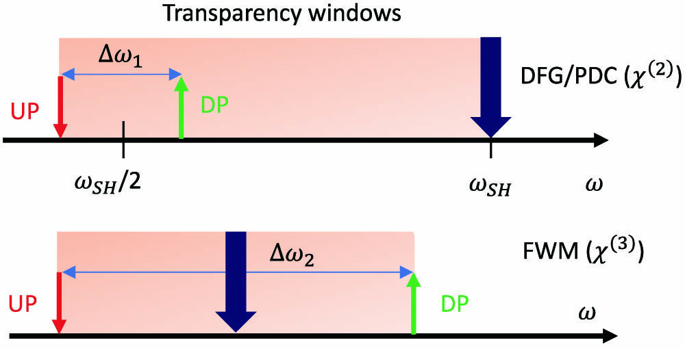
Figure 1.Operational principle of (top) and (bottom) processes for undetected-photon pair generation. UP, undetected photons; DP, detected photons; DFG, difference frequency generation; PDC, parametric down-conversion; and FWM, four-wave mixing.
In this paper, for the first time, to the best of our knowledge, we use stimulated four-wave mixing (FWM) within the highly nonlinear silicon core fiber (SCF) platform to demonstrate a robust and efficient undetected-photon imaging system. The SCFs used in this work have been tapered to control the core diameter and thus the phase-matching conditions, as well as to reduce the insertion losses [14]. Compared to traditional glass fiber systems, the SCFs offer significantly higher nonlinear coefficients, so that both amplitude and phase images can be obtained using a continuous wave 1550 nm pump source with an average power of only 48 mW within a compact geometry. The conversion bandwidth used for the imaging is 60 nm, which was defined primarily by the available components and not by the SCF transmission window. Aside from the imaging section, which is free space by necessity, the remainder of the setup is all-fiberized, improving the stability and portability of the system.
Sign up for Photonics Research TOC. Get the latest issue of Photonics Research delivered right to you!Sign up now
2. FIBER DESIGN AND FABRICATION
The SCFs used in this work were fabricated using the molten core drawing (MCD) method, which produces fibers with a uniform polysilicon core with typical diameters of 12 μm within a 125 μm diameter silica cladding [14]. To enhance the nonlinear performance, the as-drawn SCFs were tapered using a conventional glass processing workstation (Vytran GPX-3300) to obtain submicrometer core diameters. As well as reducing the core size, which acts to increase the mode confinement and tailor the dispersion properties, the tapering process also serves to improve the crystallinity of the silicon core to almost single-crystal-like quality, which reduces the overall transmission losses (see Appendix A for details). A schematic of the tapered SCF design is shown in Fig. 2(a), in which a long uniform waist region is set between two taper transition regions. The taper transitions are retained at the SCF ends to increase the input and output core diameter and thus improve the optical coupling to standard optical fibers. However, the transitions are typically kept as short as possible, around a few millimeters at each end, so only the tapered waist section of the SCF (typically one to several centimeters) must be considered for the nonlinear propagation. We note that, thanks to the high-index contrast between the SCF core and cladding, the fibers can support sharp taper transitions while still maintaining the adiabatic condition [15].

Figure 2.(a) Schematic of tapered SCF as used for stimulated FWM. (b) Calculated GVD and FOD parameters for the SCF with a 915 nm core diameter designed for a 1550 nm pump source.
Owing to their low optical transmission loss and high coupling efficiencies, the tapered SCFs have shown versatile performance for nonlinear optical applications across the conventional telecom band [16]. In this work, we chose a pump source with a wavelength of 1550 nm to generate photon pairs via stimulated FWM. To obtain high nonlinear conversion efficiencies, we targeted SCFs with a tapered core diameter of so that the pump was positioned close to the zero-dispersion wavelength, which is required for maximum conversion efficiency. The tapered waist length was selected to be 1.5 cm to obtain sufficient nonlinear conversion without introducing too much loss, which resulted in a total SCF length of 1.8 cm when including the taper transition regions. The input/output core diameters were both fixed at , and the total insertion loss at 1550 nm for this SCF was , which includes a 7.5 dB coupling loss and 1.4 dB linear transmission losses. The calculated group velocity dispersion (GVD, ) and fourth-order dispersion (FOD, ) for this waist diameter are shown in Fig. 2(b), as estimated via modal simulations using the refractive indices of silicon and silica from Frey et al. [17] and Leviton et al. [18]. As the SCFs are designed to have a GVD close to zero, it is important that the FOD is negative to compensate for the nonlinear component of the total phase mismatch, which has a small positive value [19].
3. EXPERIMENTAL SETUP
The experimental setup used to construct our classical FWM-based undetected-photon imaging system combines features of the quantum setup of Lemos et al. [1] with the classical approach of Cardoso et al. [9]. A schematic of the system is shown in Fig. 3(a), where the 1550 nm pump is a CW source, and the signal and idler are also CW at 1580 nm and 1521 nm, respectively. We note that the choice of a low-power CW pump means that two-photon absorption processes can be ignored [19], which helps to ensure the efficiency of the FWM process. Unlike the previous classical implementation [9], in which the seed laser used to produce the idler beam passes through the same nonlinear crystal twice, here we generate a strong and stable image by splitting both the pump and signal using 50:50 fiberized beam splitters (BSs) before launching into two distinct SCFs. This approach is more similar to the one used in the quantum implementation [1]. This way one has straightforward and independent control of the generated idler powers in both fibers and can make use of the coherence of the pump and signal beams (transferred to the idler beams via FWM) to produce the image.
Figure 3.(a) Experimental setup for amplitude imaging using undetected photons. For phase imaging, the PS and chopper are removed, and the detector is replaced by a camera. BS, beam splitter; PC, polarization controller; OB, object; OC, optical chopper; WDM, wavelength division multiplexer; TLF, tapered lens fiber; TF, tunable filter; and PS, phase shifter. (b) FWM spectra generated by the two SCFs during amplitude imaging. (c) Phase correlation measurement for the detected idlers, including a sinusoidal fit to the experimental data.
To make the interaction between the signal light and the object possible, a free-space section was included in the setup, in which the light is coupled out of and back into the fiber system using fiber collimators. The total coupling loss of this section was 1.05 dB, which introduced a small power difference between the signal and idler beams in the two arms. The object was fixed on a two-axis stage so that it could be scanned across the beam along the and directions perpendicular to the propagation direction of the beams. To ensure the optimum conversion efficiency, two polarization controllers (PCs) were used to align the polarization of the pump beams relative to the signals. The pump and signal beams were combined using low-loss wavelength division multiplexers (WDMs) before launching into the fundamental mode of the SCFs using tapered lens fibers, whereby the idler beams were generated via FWM. To make the system insensitive to phase noise and drifts in the pump and signal lasers, we ensured the optical path lengths of the beams from the two lasers were matched within 10 cm before launching into the two SCFs. Moreover, the fibers between the BSs and WDMs (where the pump and signal were not propagating together in the same fiber) were kept short (less than 1.5 m) and close together, so that they experienced the same temperature variation. The same approach was adopted for the fibers after the two SCFs, prior to the interference of the two idlers. Because they were only the idler beams used for imaging, the pump and signal beams were filtered out, and a PC was placed in the reference arm to align the polarization of two idlers.
When using this setup for amplitude imaging, a 50% duty cycle optical chopper connected to a lock-in amplifier (LIA) was inserted into the free-space section to modulate the DC signal for detection. A phase shifter was also placed in the object arm, just before the BS, to balance the idler phases in the two arms so that the photodetector simply recorded the sum of the idler powers. As shown in Fig. 3(b), the idler generated by was around 4.05 dB lower than that of , which corresponds to the losses induced by the chopper (3 dB) and the fiber collimators (1.05 dB). For the phase imaging, the phase shifter and chopper were removed and the photodetector was replaced by a CCD camera onto which the idlers were overlapped to generate moiré fringes [20].
To test the operation of the system, we initially used the phase shifter in place of the free-space section to mimic a simple phase-modifying object. We note that the loss of the phase shifter is only , less than in the free space system used for the imaging, which slightly improves the idler balance between the two arms. By varying the applied voltage, the phase of the probe signal laser could be adjusted between 0 and before launching into , resulting in a combined power variation for the two FWM generated idler beams shown in Fig. 3(c). The good agreement between the experimental data and a sinusoidal fit (solid curve) provides evidence of the phase correlation between the two generated idlers. The power difference between the two generated idlers limits the fringe visibility to about 60%. Thus, we conclude that the fringe visibility of 53% is mostly caused by this power imbalance. If required, the visibility could be improved by adjusting the pump or signal power for each SCF with customized BS ratios. Nevertheless, this first demonstration highlights the advantages of this classical configuration in that photon counters or single-photon sensitivity cameras are not required. The next step was to demonstrate imaging using physical objects.
4. AMPLITUDE IMAGING
First, we demonstrated amplitude imaging. For the amplitude object, we considered the “ORC” pattern shown in Fig. 4(a) cut into aluminum foil. The foil completely blocks the 1580 nm signal beam (), while the lettering is fully transparent (). The object is scanned with the signal beam over a step size of 1 mm in both the and directions. This step is slightly smaller than the resolution (), which is limited by the FWHM spot size of the collimated signal beam [21]. The resulting amplitude image is shown in Fig. 4(b), where a pump power of and a signal power of for each SCF were used. Although the shape of the image matches well with the designed pattern, the edges are not completely smooth, which is partially due to the limited resolution and step size. However, thanks to the narrow linewidth of the generated idler beams, which are estimated to be (the linewidths of the pump and signal lasers were each 10 kHz) used for the stimulated FWM, this system exhibits a coherence length of more than 4 km, making the setup very stable and robust. In future work, the resolution could be reduced to micrometer dimensions by focusing the signal beam to a small size, as done by White et al. [21], although this would require a careful redesign of the free-space section to avoid inducing instability into the setup.
Figure 4.(a) Pattern for amplitude imaging. (b) Relative amplitude image obtained with a scan step of 1 mm. The color scale shows amplitude levels.
5. PHASE IMAGING
We then turned to phase imaging. In this case an ORC pattern was laser cut in a 2 μm thick pellicle film, as shown in Fig. 5(a). The designed height of each letter is 15 mm, and the total width of the ORC pattern is 35 mm. The small bridges retained in the lettering are to avoid distortion, or curling, of the cut film. The film has a high transmission of 92% for the 1580 nm signal, and the refractive index of introduces a phase shift between the signal transmitted through the lettering. The phase image is shown in Fig. 5(b), and was obtained using the same pump and signal powers as for the amplitude image and scanned with a 1 mm step size in and . The ORC pattern can be clearly observed in the phase image, and the moiré fringes are very stable when the signal beam falls inside or outside the letters. We stress that in our system the phase correlation only depends on the signal seed due to the intrinsic phase locking of degenerate FWM; in earlier work [9], it relies on both the phases of the pump and the signal beams. Finally, when comparing the phase and intensity images directly, we attribute the slightly crisper edges of the phase image to the better quality of the phase object, which was produced via laser cutting rather than hand cutting [as shown in the photo of the amplitude object in Fig. 6(a) of Appendix A], and to the better balance between the two idler powers due to the removal of the chopper.
Figure 5.(a) Transparent object for phase imaging cut out from a pellicle film. (b) Relative phase image obtained with a scan step of 1 mm. The color scale shows phase shift levels.
Figure 6.(a) Opaque object for amplitude imaging cut out from a thick aluminum foil. (b) Calculated GVD and FOD parameters for the untapered SCF with a 12 μm core diameter.
6. CONCLUSION
In summary, we have demonstrated amplitude and phase imaging of objects by detecting classical light generated by FWM that has never interacted with the object. The results confirm that the beams produced by stimulated FWM have a high degree of spatial and phase correlation, as has been previously shown for PDC [9]. However, unlike the PDC case, FWM processes offer much more flexibility in terms of the positioning of the interacting wavelengths, which in this demonstration are all located within the telecom band where we have access to efficient fiber components, opening a route for the development of more robust and practical imaging systems. By employing our SCF platform that has been tapered to precisely control the dispersion, we have been able to take advantage of the highly nonlinear silicon core to achieve high contrast and stable images using modest powers and relatively short device lengths when compared to more traditional glass fiber systems. Moreover, thanks to the extended transmission window of the silicon core, these fibers could also be used to construct broadband systems where the object illumination is in the mid-IR region and the detection is conducted in the telecom band [13,22]. Thus, continued efforts to reduce the losses and optimize the integration of the SCFs with components that offer extended wavelength operation will help to expand the application potential for undetected-photon imaging using fiber-based nonlinear processing.
Acknowledgment
Acknowledgment. The authors would like to acknowledge support from the following funding bodies: A. C. Peacock (Engineering and Physical Sciences Research Council); U. J. Gibson (The Research Council of Norway); J. Ballato (J. E. Sirrine Foundation); J. E. Sipe (Natural Sciences and Engineering Research Council of Canada); L. Shen (National Natural Science Foundation of China); and M. Huang (Chinese Scholarships Council).
APPENDIX A: MATERIALS AND METHODS
The silicon core fibers (SCFs) used here were fabricated using the molten core drawing (MCD) method, where a silicon rod was sleeved inside a silica glass capillary that had been coated with a thin layer of calcium oxide (CaO) to form a preform. The CaO layer is used to prevent the dissolution of silica from the cladding into the silicon core and also reduces the thermal strain arising during the drawing process [23]. The fibers were produced from the preform using a conventional drawing tower, where they were heated to a temperature of and pulled down with a speed of [24]. The silicon core materials are polycrystalline in nature after drawing, with crystalline grain sizes of a few hundreds of micrometers to millimeters in length. Therefore, the optical transmission losses of these fibers are usually high ( within the telecom band) and the core diameters are typically too large (6–10 μm) for nonlinear applications.
Due to the large normal material dispersion of silicon, large core SCFs also have a normal dispersion. The calculated GVD () and FOD () for the untapered SCF with a 12 μm core diameter are shown in Fig. 6(b). Thus, to access the anomalous dispersion regime desired for FWM applications, the SCFs were tapered to reduce the core diameter to , which introduces a strong negative waveguide dispersion in the telecom band [19]. Thanks to the silica cladding, the as-drawn fibers can be tapered using a standard glass processing system (Vytran GPX3400). During the tapering process, the silicon core is completely molten, as in the MCD process, but now the drawing speed can be reduced () to control the cooling dynamics, which also helps to improve the optical properties of the core by promoting large grain (centimeters length) crystal growth [25]. The core/cladding interface of these fibers is extremely smooth (rms roughness of ), so that small core fibers (core diameters ) can be obtained with minimal interface scattering [25]. The final tapered SCFs had a waist diameter of ( and ) over a length of 1.5 cm, with input and output taper transition regions of length scaling up to facet diameters of ( and ). Due to the high core/cladding index contrast of the SCFs, the taper transitions are adiabatic even over these short lengths, so that mode coupling and radiation loss from the input fundamental mode in these regions are negligible. After tapering, the processed fiber was mounted with wax in a capillary tube to polish the input and output faces using routine fiber preparation methods.
As previously reported by Wu et al. [19], the two-photon absorption is negligible in SCFs with submicron core diameters for power levels below a few watts ( for a diameter of ), and so much higher than the powers used for imaging. The transmission losses of the tapered SCFs were estimated from the total insertion losses as the coupling loss for these input/output diameters is well established, as reported by Ren et al. [26]. The transmission measurements were conducted using the same coupling configuration as in the undetected-photon imaging experiment with the input and output powers measured using an InGaAs photodiode power sensor (Thorlabs S148C). By subtracting the coupling loss from the total insertion loss, the transmission loss can be estimated for both SCFs to be for the wavelengths used in our measurements.
References
[1] G. B. Lemos, V. Borish, G. D. Cole, S. Ramelow, R. Lapkiewicz, A. Zeilinger. Quantum imaging with undetected photons. Nature, 512, 409-412(2014).
[2] M. Gilaberte Basset, A. Hochrainer, S. Töpfer, F. Riexinger, P. Bickert, J. R. León-Torres, F. Steinlechner, M. Gräfe. Video-rate imaging with undetected photons. Laser Photon. Rev., 15, 2000327(2021).
[3] I. Kviatkovsky, H. M. Chrzanowski, E. G. Avery, H. Bartolomaeus, S. Ramelow. Microscopy with undetected photons in the mid-infrared. Sci. Adv., 6, eabd0264(2020).
[4] V. Boyer, A. M. Marino, R. C. Pooser, P. D. Lett. Entangled images from four-wave mixing. Science, 321, 544-547(2008).
[5] J. S. Dam, P. Tidemand-Lichtenberg, C. Pedersen. Room-temperature mid-infrared single-photon spectral imaging. Nat. Photonics, 6, 788-793(2012).
[6] D.-S. Ding, Z.-Y. Zhou, W. Huang, B.-S. Shi, X.-B. Zou, G.-C. Guo. Experimental up-conversion of images. Phys. Rev. A, 86, 033803(2012).
[7] K. Huang, J. Fang, M. Yan, E. Wu, H. Zeng. Wide-field mid-infrared single-photon upconversion imaging. Nat. Commun., 13, 1(2022).
[8] J. H. Shapiro, D. Venkatraman, F. N. Wong. Classical imaging with undetected photons. Sci. Rep., 5, 10329(2015).
[9] A. Cardoso, L. Berruezo, D. Ávila, G. Lemos, W. Pimenta, C. Monken, P. Saldanha, S. Pádua. Classical imaging with undetected light. Phys. Rev. A, 97, 033827(2018).
[10] A. Búzás, E. K. Wolff, M. G. Benedict, P. Ormos, A. Dér. Biological microscopy with undetected photons. IEEE Access, 8, 107539(2020).
[11] G. B. Lemos, M. Lahiri, S. Ramelow, R. Lapkiewicz, W. N. Plick. Quantum imaging and metrology with undetected photons: tutorial. J. Opt. Soc. Am. B, 39, 2200-2228(2022).
[12] S. Slussarenko, G. J. Pryde. Photonic quantum information processing: a concise review. Appl. Phys. Rev., 6, 041303(2019).
[13] X. Liu, B. Kuyken, G. Roelkens, R. Baets, R. M. Osgood, W. M. Green. Bridging the mid-infrared-to-telecom gap with silicon nanophotonic spectral translation. Nat. Photonics, 6, 667-671(2012).
[14] F. H. Suhailin, L. Shen, N. Healy, L. Xiao, M. Jones, T. Hawkins, J. Ballato, U. J. Gibson, A. C. Peacock. Tapered polysilicon core fibers for nonlinear photonics. Opt. Lett., 41, 1360-1363(2016).
[15] Y. Fu, T. Ye, W. Tang, T. Chu. Efficient adiabatic silicon-on-insulator waveguide taper. Photon. Res., 2, A41-A44(2014).
[16] D. Wu, L. Shen, H. Ren, M. Huang, C. Lacava, J. Campling, S. Sun, T. W. Hawkins, U. J. Gibson, P. Petropoulos. Four-wave mixing-based wavelength conversion and parametric amplification in submicron silicon core fibers. IEEE J. Sel. Top. Quantum Electron., 27, 4300111(2020).
[17] B. J. Frey, D. B. Leviton, T. J. Madison. Temperature-dependent refractive index of silicon and germanium. Proc. SPIE, 6273, 62732J(2006).
[18] D. B. Leviton, B. J. Frey. Temperature-dependent absolute refractive index measurements of synthetic fused silica. Proc. SPIE, 6273, 62732K(2006).
[19] D. Wu, L. Shen, H. Ren, J. Campling, T. W. Hawkins, J. Ballato, U. J. Gibson, A. C. Peacock. Net optical parametric gain in a submicron silicon core fiber pumped in the telecom band. APL Photon., 4, 086102(2019).
[20] C. Joenathan, B. Khorana. Phase measurement by differentiating interferometric fringes. J. Mod. Opt., 39, 2075-2087(1992).
[21] A. G. White, J. R. Mitchell, O. Nairz, P. G. Kwiat. “Interaction-free” imaging. Phys. Rev. A, 58, 605-613(1998).
[22] S. Signorini, M. Mancinelli, M. Borghi, M. Bernard, M. Ghulinyan, G. Pucker, L. Pavesi. Intermodal four-wave mixing in silicon waveguides. Photon. Res., 6, 805-814(2018).
[23] E. F. Nordstrand, A. N. Dibbs, A. J. Eraker, U. J. Gibson. Alkaline oxide interface modifiers for silicon fiber production. Opt. Mater. Express, 3, 651-657(2013).
[24] J. Ballato, T. Hawkins, P. Foy, R. Stolen, B. Kokuoz, M. Ellison, C. McMillen, J. Reppert, A. Rao, M. Daw. Silicon optical fiber. Opt. Express, 16, 18675-18683(2008).
[25] Y. Franz, A. Runge, H. Ren, N. Healy, K. Ignatyev, M. Jones, T. Hawkins, J. Ballato, U. Gibson, A. Peacock. Material properties of tapered crystalline silicon core fibers. Opt. Mater. Express, 7, 2055-2061(2017).
[26] H. Ren, L. Shen, D. Wu, O. Aktas, T. Hawkins, J. Ballato, U. J. Gibson, A. Peacock. Nonlinear optical properties of polycrystalline silicon core fibers from telecom wavelengths into the mid-infrared spectral region. Opt. Mater. Express, 9, 1271-1279(2019).
[27] M. Huang. Dataset for the publication ‘Classical imaging with undetected photons using four-wave mixing in silicon core fibers(2022).


