A passband frequency-electable microwave photonic multiband bandpass filter based on a cascaded fiber Sagnac loop is presented and experimentally demonstrated. A broadband light is sliced by the cascaded fiber Sagnac loop, which serves as a spectrum slicer. After broadband light passes through the spectrum slicer, the sliced broadband light will have the varied periodical spectral characteristics that will cause a transmitted spectral distribution with uniform or multiple periods, then will be modulated by an optical phase modulator and delayed by a dispersive medium. Therefore, a frequency-band-selectable microwave photonic multiband bandpass filter with a suppressed baseband is achieved that can be switched between the single-passband, dual-passband, and triple-passband state. The presented filter exhibits a maximal out-of-band rejection ratio of about 30 dB.
Microwave photonic filters (MPFs) is a hot research topic and is found to have potential application in fields such as radar systems, wireless communication, and radio astronomy[1]. MPFs have some unique and attractive advantages compared with electrical filters such as low loss, light weight, wide tunable bandwidth range, agile tunability, rapid reconfigurability, and immunity to electromagnetic interference (IEM)[2,3]. Various studies for designing the MPF have been intensively reported in recent years. The technique based on two different optical sources and a polarization modulator (PolM) has been used to achieve a tunable single-bandpass filter[4]; the technique based on self-phase modulation spectrum broadening[5], a polarization beam interferometer[6], or alternative liquid crystal layers[7] is used to get an MPF; and the techniques based on an optical phase modulator (PM) incorporated with a phase-shifted fiber Bragg grating (PS-FBG)[8], a stimulated Brillouin scattering (SBS)[9], a Fabry–Pérot semiconductor optical amplifier (FP-SOA)[10], and some spectrum-shaped optical frequency combs[11] are all used to implement a single passband filter. However, these MPFs are single-passband MPFs, and many papers have also proposed to implement multi-passband MPFs. A highspeed optically controlled microwave photonic reconfigurable dual-band filter is presented that is achieved by using a Lyot loop filter for spectrum slicing and the ultrafast nonlinear polarization rotation (NPR) effect in an SOA for highspeed tuning[12]. For a dual-passband MPF based on a spectrally sliced broadband optical source (BOS) that is sliced by a fiber Mach–Zehnder interferometer (FMZI), the dual-passband frequency response has been realized by utilizing two dispersive fiber delay lines of different length and recombining two groups of delayed samples on the photodetector (PD)[13]. A microwave photonic multiband bandpass filter with three reconfigurable passbands has also been demonstrated, where the passband reconfigurability is achieved by manually adjusting the polarization controllers (PCs)[14]. Moreover, a tunable and selectable multiband MPF utilizing reflective and cascaded FMZI has been demonstrated, the passband selection can be realized via rotating the PCs within reflective and cascaded FMZIs, and the central frequency of the passband can be tuned by changing the length of the variable optical delay line (VODL) in the FMZI[15].
In this Letter, a passband frequency-selectable microwave photonic multiband bandpass filter based on a cascaded fiber Sagnac loop is proposed. The cascaded fiber Sagnac loop with changeable and interleaving comb spacing corresponding to the comb spectrum that is used as the filter taps of the MPF to realize the frequency-band-selectable operation. The comb spacing of the cascaded fiber Sagnac loop structure can be controlled by adjusting the PCs in the loop. Therefore, the proposed filter shows three different passband states, which are the single-passband state, dual-passband state, and triple-passband state, respectively. All of these frequency responses have no baseband resonance because of the phase modulation. Furthermore, the center frequencies and bandwidths of the proposed filter can be adjusted by employing different lengths of dispersive medium. It also has some advantages such as simple structure, easy implementation, good tunability, and flexible passband selectivity.
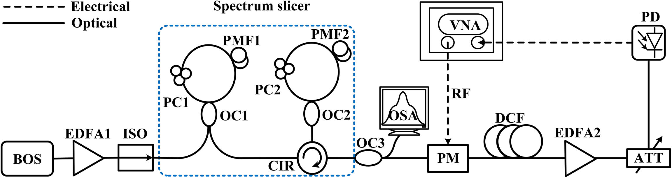
The experimental setup of the proposed passband frequency-selectable microwave photonic multiband bandpass filter is shown in Fig. 1. A broadband light emitted from a BOS is amplified by an erbium-doped fiber amplifier (EDFA) and then spectrally sliced by the spectrum slicer; the generated comb spectrum works as a multiwavelength source. Then, the sliced broadband light is modulated by a RF input signal through an optical PM. A coil of dispersion compensating fiber (DCF) is used to introduce a time delay for different wavelengths[16–18], and then the modulated signal is fed into a PD for photoelectric conversion. In the experiment, a vector network analyzer (VNA) has two functions, one is used as the RF input and another is measuring the frequency response of the system.
Sign up for Chinese Optics Letters TOC. Get the latest issue of Chinese Optics Letters delivered right to you!Sign up now
Figure 1.Schematic diagram of the proposed switchable MPF.
The spectrum slicer as shown in Fig. 1 (dashed box) is a modified structure of two cascaded first-order fiber Sagnac loops[14]. Compared with a second-order fiber Sagnac loop structure, the cascade structure has a higher extinction ratio of the comb spectrum. Mathematically, the theoretical basis of the spectrum slicer is according to the Jones algorithm. The reflectivity function expression and the transmissivity function expression of the fiber Sagnac loop can be deduced as[1]where is the coupling coefficient of optical coupler (OC), is the light polarization angle, is the angle between fast axis and slow axis of polarization-maintaining fiber (PMF), is the angle between PMF and the single mode fiber, , in which is the equivalent refractive index difference of the fast axis and slow axis, is the length of PMF, and is the wavelength. In order to simplify the function expression, we set , , and the function expression can be written as
By carefully adjusting (PC1 and PC2 in the experiment), the wavelength spacing of the transmission spectrum can be switched among the simple-period state, the dual-period state, and the triple-period state. The sliced broadband light at the output of the spectrum slicer is modulated by an optical PM with modulation indexes of and for the two first-order modulation sidebands, respectively. Then the modulated signal propagates through a dispersive medium with the transfer function[19]
The overall system response is where is radio frequency (RF) signal frequency, and is the conjugate of . , is the conversion of , respectively[20].
The layout and the experimental setup for the proposed filter are shown in Fig. 1. A center wavelength of the BOS (COF-C/L-10-FC) located at 1567 nm with a flat spectral distribution and the bandwidth covers the band. The EDFA1 (KG-EDFA-P-O-D-FA) is followed by the BOS to provide an optical gain. An isolator (ISO) is used to prevent the light back from the spectrum slicer. The broadband light emitted from the BOS is launched into a spectrum slicer including two cascaded first-order fiber Sagnac loops. The first fiber Sagnac loop consists of a 3 dB OC1, PC1, and a piece of 2 m PMF1, thus a wavelength spacing of about 2.75 nm can be obtained at the output port of OC1. The following fiber Sagnac loop including a circulator (Cir), a 3 dB OC2, and a 4 m PMF2 is used to achieve a wavelength spacing of about 1.15 nm at the output port of Cir. Therefore, by cascading the two first-order fiber Sagnac loops, different wavelength spacings can be obtained by adjusting PC1 and PC2 in the spectrum slicer. After passing through the spectrum slicer, the light is split into two branches by an OC3 (10:90). One branch (10%) is injected into an optical spectrum analyzer (OSA, Anritsu MS9740A) with a resolution of 0.2 nm for observation, another branch (90%) is sent to an optical PM (Photoline, MPZ-LN-20) for phase modulation and is dispersion delayed by a coil of DCF (DCF-G.625) whose length is 1.025 km. Before being injected to a PD (u2t, XPDV2120R) for optical-to-electrical conversion, the optical signal propagates through an EDFA2 and an attenuator (ATT). The EDFA2 and ATT are used to keep the input power into the PD less than 0 dBm for the sake of security of the system. The sweeping RF signal from a VNA (CETC, AV3629D) with a maximum sweeping frequency of 20 GHz is used as the input RF signal source and the output signal of the PD is fed back to the VNA for measuring the frequency response.
The comb spectra of the sliced broadband light are shown in Fig. 2. By adjusting the PC1 and PC2, three different comb spacings and different envelopes of sliced spectrum are measured by the OSA, respectively. The frequency response of the proposed filter generated from the corresponding optical comb spectra are measured by a VNA. The DCF with a dispersion coefficient of −140.57 ps/(nm·km) is used as the dispersive medium. In Fig. 3(a), a triple-period state comb spectrum is observed. In Fig. 3(b) the corresponding frequency responses of center frequencies at 2.36, 4.71, and 7.15 GHz when using a 1.025 km DCF are achieved, and in Fig. 3(c), the frequency responses of center frequencies at 1.17, 2.36, and 3.52 GHz when using a 2.05 km DCF are obtained, respectively. In Fig. 4(a), the comb spectrum is tuned to a dual-period state by properly adjusting PC1 and PC2, and both the frequency responses with center frequencies at 4.71 and 7.15 GHz when using a 1.025 km DCF and center frequencies at 2.36 and 3.52 GHz when using a 2.05 km DCF are shown in Figs. 4(b) and 4(c). In Figs. 5(b) and 5(c), via rotating PC1 and PC2, the MPF is tuned to a single-bandpass state that only presents one passband with a center frequency at 4.71 GHz when using a 1.025 km DCF, and a center frequency at 2.36 GHz when using a 2.05 km DCF, respectively. Due to the limitation of experimental conditions, the BOS is not shaped before the spectrum slicer, which leads to the shapes of the frequency response being greatly influenced by the envelope of the sliced spectrum, especially under the conditions of a dual-passband state. The center frequencies and bandwidths of the MPF can be adjusted by using different lengths of DCF. The reason is that the taps suffer more transmission loss in a longer fiber, and the frequency response gets a larger suppression when closer to dc due to phase modulation[21]. The width of the frequency response is also determined by the optical-source bandwidth. Therefore, for the same optical-source bandwidth, the narrower bandwidth of the frequency response is observed in the case of using a longer DCF.
Figure 2.Comb spectra of the sliced broadband light.
Figure 3.Triple-period state comb spectrum and the corresponding frequency response. (a) A triple-period state comb spectrum, (b) the frequency response of the center frequency at 2.36, 4.71, and 7.15 GHz using a 1.025 km DCF, and (c) the frequency response of the center frequency at 1.17, 2.36, and 3.52 GHz using a 2.05 km DCF.
Figure 4.Dual-period state comb spectrum and the corresponding frequency response. (a) A dual-period state comb spectrum, (b) the frequency response of the center frequency at 4.71 and 7.15 GHz using a 1.025 km DCF, and (c) the frequency response of the center frequency at 2.36 and 3.52 GHz using a 2.05 km DCF.
Figure 5.Simple-period state comb spectrum and the corresponding frequency response. (a) A simple-period state comb spectrum, (b) the frequency response of the center frequency at 4.71 GHz using a 1.025 km DCF, and (c) the frequency response of the center frequency at 2.36 GHz using a 2.05 km DCF.
In conclusion, we demonstrate a passband frequency-selectable microwave photonic multiband bandpass filter. The RF responses show three passband characteristics due to the three optical comb spectra by adjusting the PCs in the cascaded fiber Sagnac loop. The proposed filter shows a good passband quality of providing a good filter selectivity and the maximal out-of-band rejection ratio is about 30 dB without the baseband resonance because of the phase modulation. If the device and equipment in the system are further optimized, a frequency-band-selectable microwave photonic multiband bandpass filter with more passbands of higher frequencies can be achieved.