State Key Laboratory of High Performance Complex Manufacturing, College of Mechanical and Electrical Engineering, Central South University, Changsha 410083, China
Xinran Dong, Zheng Xie, Yuxin Song, Kai Yin, Dongkai Chu, Ji’an Duan. High temperature-sensitivity sensor based on long period fiber grating inscribed with femtosecond laser transversal-scanning method[J]. Chinese Optics Letters, 2017, 15(9): 090602
Copy Citation Text
We propose a high temperature-sensitive long period fiber grating (LPFG) sensor fabricated by using the femtosecond laser transversal-scanning method. The femtosecond pulses scan over the whole fiber core and some part of the cladding region; the modified regions are more extended. It is found that the LPFG-I fabricated by the transversal-scanning method shows higher temperature sensitivity and better temperature uniformity than that of LPFG-II written by the femtosecond laser point-by-point method. The LPFG-I with a temperature sensitivity of 75.96 pm/°C in the range of 25°C–400°C is measured. Moreover, in the range from 400°C to 800°C, a higher temperature sensitivity of 148.64 pm/°C and good linearity of 0.99 are achieved, while the temperature sensitivity of LPFG-II is only 95.55 pm/°C. LPFG-I exhibits better temperature characteristics, which, to the best of our knowledge, has the highest sensitivity in silica fiber temperature sensors.
Optical fiber sensors exhibit many features such as immunity to electromagnetic interference, high sensitivity, small size, low back-reflection, low cost, and multiplexing capabilities, which have attracted increasing attention in the sensing fields, including monitoring temperature, strain, bending, and refractive index[1–4]. Recently, various sensors for temperature sensing based on the long period fiber gratings (LPFGs)[5,6], fiber Bragg gratings (FBGs)[7], Mach–Zehnder interferometers (MZIs)[8], Fabry–Perot interferometers (FPIs)[9], Saganac[10], D-shaped fibers[11], and other types of sensors[12,13] have been developed. The temperature sensitivity of the LPFG depends mainly on the thermo-optic coefficient and thermal expansion coefficient of fiber materials, as well as the order cladding modes[14]. In order to improve the temperature sensitivity, some research works have been carried out. Smietana et al.[15] has fabricated LPFGs with short grating periods in boron co-doped fibers, where the purpose is to obtain higher-order cladding modes. Zhou et al.[16] has used the atomic layer deposition technology to deposit high index nanofilm () on the LPFG surface to improve the thermo-optic effect. However, the above methods for increasing temperature sensitivity are either to choose more expensive special fibers or increase the nano-coating process, which is complex and requires special equipment.
The LPFG can be fabricated by electric discharge[15], laser irradiation[17], mechanical micro-bending[18], and ultraviolet laser irradiation[19]. However, femtosecond lasers present unique advantages in three-dimensional (3D) structuring of transparent materials; especially in the processing of optical fiber sensors because of extremely short widths as well as high peak power, but almost without thermal affects, which results in a permanent refractive index modulation increase in fiber, owing to nonlinear multiphoton absorption[20–22]. Previous research on the high temperature characteristics of an LPFG has mostly focused on the LPFG inscribed by a laser[5,23]. Recently, the temperature sensitivity of an LPFG in a standard single-mode fiber (SMF) fabricated by a femtosecond laser is relatively low and most reports focused on the low temperature range[24,25].
In this work, we have investigated an LPFG with high temperature sensitivity of about 148.64 pm/°C in the range of 400°C–800°C fabricated by the femtosecond laser transversal-scanning method, which, to the best of our knowledge, has the highest sensitivity in silica fiber temperature sensors. In addition, we have found that increasing the scanning area of fiber cladding can enhance the temperature sensitivity significantly. In the experiment, the temperature sensitivities of the LPFG written by the point-by-point method are only 43.68 pm/°C in the range of 25°C–400°C and 95.55 pm/°C in the range of 400°C–800°C. In addition, the LPFG obtained by the transversal-scanning method has shown better temperature uniformity, which is desirable for temperature sensors.
Sign up for Chinese Optics Letters TOC. Get the latest issue of Chinese Optics Letters delivered right to you!Sign up now
When the ambient temperature has changed, the effective refractive index of the fiber core and cladding of the LPFG will change. The grating period will also change due to the expansion of the temperature effect. The resonant wavelength of an LPFG generated by the th cladding modes can be expressed as follows[25]: where m and are the mth-order resonant wavelength and the grating period, respectively. , , and are the effective refractive index of fiber core and cladding, respectively.
The change of grating period is related to the thermal expansion coefficient of fiber, which can be expressed as follows: where is the thermal expansion coefficient of fiber. For conventional telecommunication SMF-28, the value of is about . Also, the effective refractive index of the fiber core and cladding and with temperature is expressed as where and are the thermo-optic coefficients of fiber core and cladding, respectively. For SMF-28, the corresponding values for and are and , respectively.
Considering the existance of waveguide dispersion and mode dispersion in transmission, Eq. (1) can be simply written as where and describe the waveguide dispersion and the temperature-sensitivity factor, respectively, which are defined by Ref. [26] as
From Eq. (5), we can see that the temperature sensitivity of the LPFG strongly depends on and . is related to grating period and cladding mode order , as shown in Eq. (6). However, for resonant wavelengths of low-order cladding modes (), the values of are almost the same[26]. In general, the effect of the thermal expansion effect of the fiber can be neglected because and are much larger than . Therefore, the temperature sensitivity of the LPFG mainly depends on .
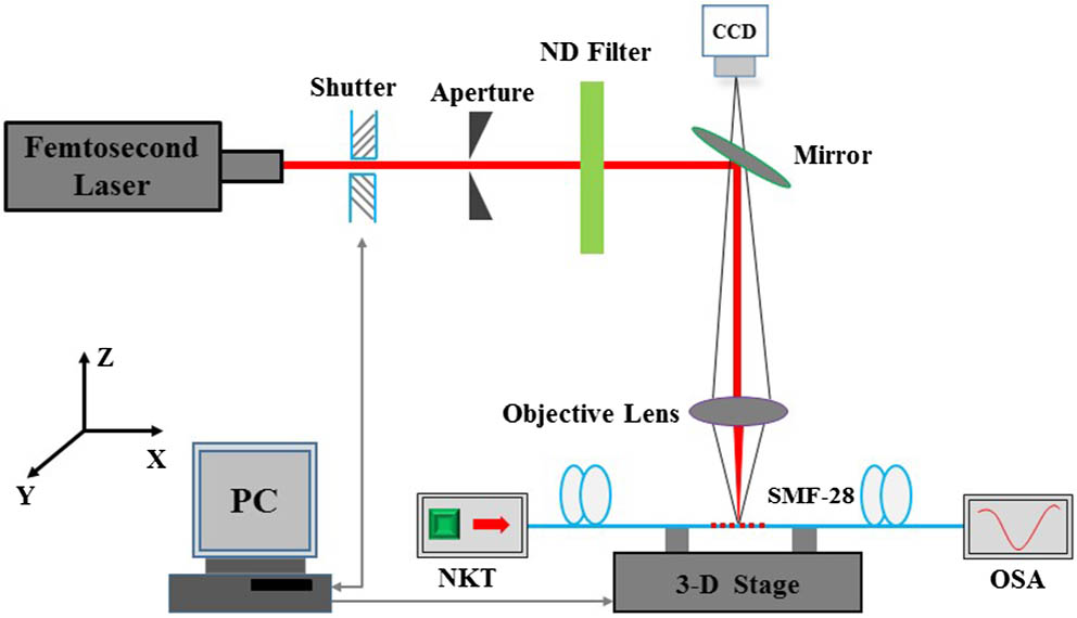
Figure 1 shows the schematic diagram of the femtosecond laser fabrication system. An amplified 800 nm femtosecond laser (Spectra Physics, Inc) of 120 fs at a repetition rate of 1 kHz is used to fabricate LPFGs in an SMF (Corning SMF-28), which is mounted on a computer-controlled translation stage with 5 nm resolution. The laser beam is tightly focused into the fiber core by a microscope objective lens (), and the single pulse energy is about 2 μJ, measured before the objective lens. We use a broad band light source (NKT) with a wavelength range from 600 to 1700 nm and an optical spectrum analyzer (OSA, Agilent 86142B, wavelength range 600–1700 nm) with a resolution of 0.06 nm to trace the transmission spectrum. The paths of the femtosecond laser point-by-point method and transversal-scanning method are shown in Fig. 2. During the experiment, the scanning speed and grating period are the same as 20 μm/s and 590 μm, respectively. Compared with the point-by-point method, the written parameters of the new method are flexible. The whole fiber core and part of the cladding region are modified by the laser so that the modified region is larger. Figure 3 shows the scanning electron microscope (SEM) images of the fiber cross section of the laser modified region with two different inscription methods. It can be seen that the modified region fabricated by the transversal-scanning method are more extended than that by the point-by-point method.
Figure 1.Schematic diagram of femtosecond laser fabrication system.
Figure 4 shows the transmission spectra of LPFGs fabricated by two different methods. LPFG-I with a dip of as well as the resonant wavelength at 1287 nm is fabricated by the transversal-scanning method, while LPFG-II with a resonant wavelength of 1490 nm is fabricated by the point-by-point method. The parameters of two LPFGs are the same except for the grating periodicity. LPFG-I is only 30 periodicities, which is a total length of 17.7 mm, but LPFG-II is 50 periodicities.
Figure 4.Transmission spectra of LPFGs fabricated by two different methods (LPFG-I with transversal-scanning method and LPFG-II with point-by-point method).
The LPFGs are put into a tube furnace for temperature measurements and are heated to 800°C at the rate of about 9°C/min. After remaining there for 2 h to remove part of the residual stress in gratings, they are cooled to room temperature in air. The transmission spectra changes of the LPFGs are recorded with intervals of 100°C. As the temperature increases, the transmission spectra changes of LPFG-II are shown in Fig. 5(a). The resonant peak shifts toward longer wavelengths from 1492.14 to 1545.77 nm when the temperature is increased from 20°C to 800°C. The wavelength variation is 53.63 nm. The temperature-sensitivity function fitting can be perfectly divided into two parts by linear fitting, as shown in Fig. 5(b). The wavelength shift slopes are 43.68 and 95.55 pm/°C with a linearity of 0.9759 and 0.9950 in the range of 20°C–400°C and 400°C–800°C,respectively. From Fig. 6(a), we can see that the wavelength variation of LPFG-I fabricated by the transversal-scanning method is 88.19 nm (from 1288 to 1376.5 nm) with temperature increases, which is larger than that of LPFG-II. Also, the temperature-sensitivity function fitting of LPFG-I can be well divided into two parts by linear fitting, as shown in Fig. 6(b). A temperature sensitivity of 75.96 pm/°C with a linearity of 0.9475 in the range of 20°C–400°C is obtained by linear fitting. Moreover, in the higher temperature range, LPFG-I has exhibited a sensitivity of 148.64 pm/°C with a good linearity of 0.9934, which, as far as we know, is the highest in silica fiber temperature sensors based on LPFGs. It is higher than that in a SMF fabricated by a laser (113 pm/°C)[27], as well as a femtosecond laser (90 pm/°C)[24], and the micro-core-offset (MCO) LPFG temperature sensor fabricated by the cleaving–splicing method (97.7 pm/°C)[28].
Figure 5.(Color online) (a) Transmission spectra of LPFG-II with temperature increases; (b) resonant wavelength and attenuation change as a function of temperature change.
Figure 6.(Color online) (a) Transmission spectra of LPFG-I with temperature increases; (b) resonant wavelength and peak attenuation change as a function of temperature change.
In addition, the peak attenuation of LPFG-II is decreased slowly as the temperature increases, which changes from to . However, LPFG-I has shown a fluctuating trend, and the variation is relatively small, whose attenuation ranges from to .
According to the fiber coupling mode theory, the resonant wavelengths of LPFG-I and LPFG-II are and cladding modes. For LPFG-I and LPFG-II, the values of are almost the same because they are both low-order cladding modes (), as well as the same grating period. On the one hand, the effective refractive index of cladding mode of LPFG-I will be much larger than that of LPFG-II, because some part of the cladding region of LPFG-I are modified by laser pulses using the transversal-scanning method. Therefore, the of LPFG-I will be larger, according to Eq. (7), so LPFG-I will exhibit higher temperature sensitivity. On the other hand, assuming that the thermal expansion effect for gratings are considered, LPFG-I can absorb more heat in the same heating time because of its larger modified areas, and the thermal expansion effect of LPFG-I will be more significant. Additionally, the fiber cladding is more sensitivite to the external environment perturbation because of the photo-elastic effect[29]. For LPFG-I, the femtosecond pulses scan over the whole fiber core, and the modified areas are more extended, which lead to the inhomogeneity of strain distribution profiles along the fiber cross section more obvious, making the photo-elastic effect enhanced. With that in mind, LPFG-I has exhibited higher temperature sensitivity than is reasonable.
Figure 7 shows the changes of Δ variations for LPFG-I and LPFG-II as the temperature increases. It can be seen that the change of the effective index variations of LPFG-I is much larger as the temperature increases, so the wavelength of LPFG-I will be more sensitivite to the temperature change. Also, the change is larger when higher temperatures are applied. So, the two LPFGs show higher sensitivity in higher temperature ranges (400°C–800°C), as shown in Figs. 5(b) and 6(b).
Figure 7.(Color online) Changes of Δ variations for LPFG-I and LPFG-II as the temperature increases.
Figure 8 shows the transmission spectra change before heating at 20°C and cooling down to 20°C. It can be seen that the spectrum of LPFG-II is deteriorated slightly after cooling, and the resonant wavelength shifts about 1.92 nm toward the shorter wavelength direction, while the spectrum of LPFG-I is almost identical to the original spectrum, as shown in Fig. 7(b). LPFG-I has expressed better temperature uniformity, which indicates that LPFG-I is more suitable for high temperature sensing applications.
Figure 8.(Color online) Transmission spectra of (a) LPFG-II and (b) LPFG-I before heating at 20°C and cooling down to 20°C, respectively.
In this Letter, a high temperature sensor based on LPFG-I fabricated by femtosecond laser transversal-scanning method is demonstrated. Compared with LPFG-II obtained by the point-by-point method, LPFG-I shows higher temperature sensitivity and better spectrum characteristics after cooling. The sensor has an experimental temperature sensitivity of 148.64 pm/°C with a good linearity of 0.9934 in the range of 400°C–800°C by linear fitting, while the temperature sensitivity of LPFG-II is only 95.55 pm/°C. Moreover, the reason why the temperature sensitivity of LPFG-I can be enhanced is mainly due to increased scanning areas making the photo-elastic effect enhanced. The contrast experiment results show that increasing the modified region of the LPFG is a simple and effective way to improve the temperature sensitivity.
Xinran Dong, Zheng Xie, Yuxin Song, Kai Yin, Dongkai Chu, Ji’an Duan. High temperature-sensitivity sensor based on long period fiber grating inscribed with femtosecond laser transversal-scanning method[J]. Chinese Optics Letters, 2017, 15(9): 090602