• Chinese Optics Letters
  • Vol. 17, Issue 9, 090603 (2019)
Xiaotong Zhang1, Shitai Yang1, and Libo Yuan2、*
Author Affiliations
  • 1Key Laboratory of In-Fiber Integrated Optics, Ministry of Education, College of Physics and Optical Engineering, Harbin Engineering University, Harbin 150001, China
  • 2Photonics Research Center, School of Electric Engineering and Automation, Guilin University of Electronics Technology, Guilin 541004, China
  • show less
    DOI: 10.3788/COL201917.090603 Cite this Article Set citation alerts
    Xiaotong Zhang, Shitai Yang, Libo Yuan. Optical-fiber-based powerful tools for living cell manipulation [Invited][J]. Chinese Optics Letters, 2019, 17(9): 090603 Copy Citation Text show less

    Abstract

    By using a specialty optical fiber, a series of powerful microparticle manipulation tools, including optical tweezers, a micro-optical hand, and an optical gun, are developed and demonstrated. In this paper, a review of our research activities on the optical manipulation of microparticles is presented. In particular, we will describe a kind of specialty optical fiber designed and fabricated for building optical trapping and manipulating tools. The performances of annular core fiber-based optical tweezers, a multicore fiber-based micro-optical hand, and a coaxial dual waveguide fiber-based optical gun are demonstrated as examples of applications and discussed in detail. The fiber can be used in cell manipulation in life science and drug response in medicine.

    1.  INTRODUCTION

    In the early 17th century, German astronomer Kepler hypothesized that comet tails point away from the sun due to the force of solar radiation. Moreover, Maxwell’s electromagnetic theories also explain the light itself can produce radiation pressure. The development of optical manipulation technology began with the emergence of the laser beam in the 1960s. Ashikin, as a pioneer in 1970[1], first reported, to the best of our knowledge, the experimental results of accelerating suspended particles in liquid by radiation pressure produced by light. The discovery led to a new understanding of radiation pressure caused by light. In the same year, he and Dziedzic proposed optical levitation[2] by two counterpropagating laser beams. As an important milestone in 1986, Ashkin and his colleagues first observed, to the best of our knowledge, contactless particle trapping in three dimensions[3] by a single-beam gradient force and demonstrated that light could manipulate the living body without injury. This finding paved a convenient way for researching the microworld and even the nanoworld. It opened the door to light manipulation. Ashkin was awarded the Nobel Prize in Physics in 2018, which is evidence that optical tweezers and optical manipulation have become an important part of many fields of science, particularly the fields of cell biology[46], chemistry[7,8], colloid science[9], physics[1013], and even sensing[14].

    It is well-established that a cell is the basic unit of life. The study of cells can lead to a better understanding of the differences between living organisms as well as a better understanding of ourselves. Since Ashkin successfully trapped and manipulated the yeast cells by optical trapping[15], it has opened the door to intensive research of cellular functions. Various means have been developed for cell and organelle manipulation in combination with optical tweezers, including movement, sorting, and fusion. Trapping and manipulating red blood cells in blood capillaries of living animals has been demonstrated[16], which indicates that optical tweezers have become powerful tools in the study of living cells.

    A typical optical tweezers system consists of four parts, including the optical trapping device, mechanical measurement device, image capture device, and optical potential well displacement operation device[17]. The trapping device mainly refers to the laser, the beam expander, and the objective lens. The light from the laser expands and converges through large numerical apertures (NA) to generate the trap light spot. The mechanical measurement device usually employs a four-quadrant detector to measure the displacement or force of the particle. The charge coupled device (CCD) or the complementary metal oxide semiconductor (CMOS) can be used for image capture.

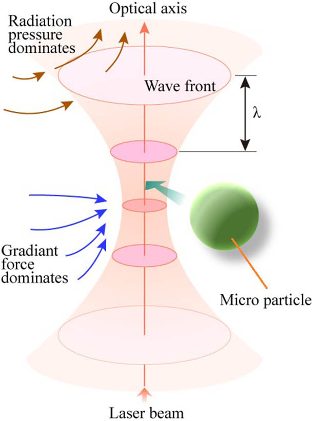
    Optical manipulation techniques can use a single light beam, a dual light beam, and even a multilight beam. Near the focus of the light beam, the forces have an effect on the particle. These forces can be divided into two types: (1) the scattering force along the propagation direction of the light beam to push the particle away, and (2) the gradient force along the gradient of the light field to pull the particle to the strongest position of the light field gradient. The basic principle of the optical trap is that the gradient force is larger than the scattering force, so the particle can be captured closed to the center of the focus spot. As Fig. 1 shows, a microparticle near the focus point is trapped by the gradient force.

    Stable 3D optical trapping near the focus area, where the gradient force dominates the micro-particle[17].

    Figure 1.Stable 3D optical trapping near the focus area, where the gradient force dominates the micro-particle[17].

    Generally, the theoretical models mainly depend on the size of the microparticles being trapped. The models can be divided into three cases. When the diameter d of the particle is much larger than the wavelength λ of the laser (dλ), including particles in the Mie regime (d>10λ), the ray optics model is reliable. When the diameter d is much smaller than the wavelength λ (dλ), including particles in the Rayleigh regime (d<0.4λ), the electromagnetic-field model is adopted[1820]. In the third case, the diameter d of the particle is comparable with the wavelength λ. In this regime, the particle is easy to optically trap in the experiment. It attracts researchers’ interests to investigate these mesoscopic objects. However, there is no corresponding appropriate theory to calculate the force in this regime. A common solution method in the field of computational electromagnetics is solving Maxwell’s equations by various numerical algorithms, for instance, the finite element method (FEM)[21,22], discrete dipole approximation (DDA) method[23,24], finite difference time domain (FDTD) method[2527], and T-matrix method[28,29]. According to the above methods, the optical force applied to the particle can be calculated by solving for the scattering optical field.

    Optical tweezers have been developed over thirty years generating various types, such as novel-beam optical tweezers, near-field optical tweezers, hologram tweezers, plasmonic optical tweezers, and fiber optical tweezers[3036]. This article principally introduces the fiber optical tweezers made by our laboratory. Optical fiber tweezers can manipulate cells without damage. By combining the optical fiber tweezers with microfluid, a bio lab can be made by investigation of the living cell.

    2.  FIBER OPTICAL TWEEZERS

    2.1.  Why Fiber Optical Tweezers?

    We can divide optical tweezers into two types: traditional optical tweezers and fiber optical tweezers. Traditional optical tweezers often include several necessary optical elements such as an objective lens with high NA, a beam expander, a dichroic mirror, a light source, and reflective mirrors. The cost of traditional optical tweezers is high. Fiber optical tweezers usually include a light source and an optical fiber; the microscope only works as an observation device. Thus, fiber optical tweezers are usually simpler and cheaper than traditional tweezers.

    One can find the differences between traditional optical tweezers and fiber optical tweezers from the comparison shown in Table 1. The traditional optical tweezers show merits but also some limitations. Although the trapping force is large, the disadvantages are also obvious, such as the large size, the small field of view, and the short working distance. The appearance of the optical fiber makes another case for optical tweezers. Beyond the well-known merits of the fiber, it is also flexible, has a small size, has a compact structure, is immune to electromagnetic interference, is easy to integrate, and is biocompatible. The optical fiber tweezers natively have a small mode field, can separate the optical well, and manipulate away from an optical microscope with an independent optical path. In 1993, Constable et al. presented that they had successfully trapped small dielectric spheres and living yeast by a light well-formed by two aligned optical fibers[36]. It enlightened researchers to use the optical fiber to implement different kinds of trapping, manipulation, rotation, and arrangement of particles.

    Spatial Optical TweezersFiber Optical Tweezers

    Complex structure

    Large size

    Large trapping force

    Limited operating area

    Unsuitable for trapping in vivo

    Multitrapping and complicated manipulation by using SLM

    Expensive

    Various optical fields

    Simple structure

    Compact size

    Small trapping force

    Trapped particle moving with optical fiber

    High flexibility

    Suitable for trapping in vivo

    Simple multitrapping and low operability for multiparticles

    Low cost

    Limited optical field

    Single-particle trapping and manipulation

    Table 1. Comparison of Spatial Optical Tweezers and Optical Fiber Tweezers

    Traditional optical tweezers are powerful tools for particle manipulation, especially when they are combined with a spatial light modulator (SLM). In the latter case, multitrapping and complicated manipulation can be realized. Although optical fiber tweezers are insufficient for manipulating multiparticles at will, they can trap several particles and arrange them simultaneously[3739].

    Traditional optical tweezers show much promise in living cell manipulation; however, they are bulky, and the fixed light path makes them unsuitable for cell trapping in vivo. Optical fibers are flexible and small in diameter. They can be introduced into the blood vessel along with medical needles or reach diseased tissue through a natural orifice. Optical tweezers are very attractive for medical applications in vivo.

    2.2.  Fabrication of Optical Fiber Tweezers

    The key goal of optical tweezers is to create a large divergence angle to form enough optical gradient force. However, the output optical field from the unprocessed fiber tip usually has a narrow divergence angle, which cannot generate a powerful trapping force. Thus, understanding how to construct a focusing optical field with large divergence angle at the fiber tip is important. There are two key elements: optical fiber type and fiber tip structure.

    Table 2 shows the comparison of different fiber tip fabrication methods, and a representative work with a different type of optical fiber is selected for every method.

    Type of Fabrication MethodAdvantagesDisadvantagesRepresentative WorksReference
    Polishing/grindingEasy to implement, low cost, reproducibility, no contactLow focusing power, time-consuming (min–hours)[40]
    Fusion and drawing/thermal pullingLow cost, time saving (min)Tip shape limitation[41]
    Chemical etchingLow cost, reproducibilitySomewhat dangerous[42]
    High-resolution micromachining (fs laser/focused ion beam/two-photon lithography)Complex construction designsExpensive, time-consuming (min–hours)[43]
    Photo polymericLow cost, time-saving (sec–min), good reproducibilityAging, environmentally unfriendly [44]
    Microsphere gluingLow cost, good reproducibility, no contactAging[45,46]

    Table 2. Comparison of Different Fiber Tip Fabrication Methods[40]

    Optical fiber end face polishing is a traditional optical fiber micromachining technology, which is usually used in the coupling lens of an optical fiber connector to improve the coupling efficiency of the light beam. The optical fiber end face is formed by grinding and polishing to achieve a large convergence angle. In 1997, Taguchi et al. used the method of mechanical polishing to prepare a spherical microlens at the tip of a single-mode fiber (SMF), which compressed the light beam in the SMF to form a single trapping point, but the gradient force of the optical tweezers was weak[47]. In 2012, we used a polishing method to form a cone frustum at the tip of a multicore fiber and a ring core fiber[41]. The light beams propagated in every core can be reflected at the surface of the cone frustum, and the output light beam converged to form a high-intensity point with a high-energy gradient and, therefore, a greater gradient force. The grinding and polishing process was lowcost and well-developed, and had high repeatability. However, a long polishing time was necessary to make the cone-frustum surface smooth.

    Thermal pulling is also a common manufacturing technique for fiber optical tweezers. Generally, the fiber core at the tapered tip becomes smaller, and the output beam is compressed with a large divergence angle, so a particle can be trapped at the fiber tip. We have used an SMF[48] and a twin-core fiber[42] to make fiber optical tweezers using a thermal pulling method. It is fast and convenient to make fiber optical tweezers by thermal pulling; however, the tip of optical fiber tweezers should be an abrupt taper, and it is difficult to make an abrupt taper with the desired parameters.

    Hydrofluoric acid is corrosive to silicon dioxide, so chemical etching can also be used to shape the fiber tip to form fiber optical tweezers. In 2011, Mishra et al. realized a microaxicon on the tip of the SMF by chemical etching, which converted the Gaussian beam transmitted in the SMF into a Bessel beam output, resulting in the capture of two-photon fluorescence excitation of a single particle[7]. In 2012, we prepared a microstructure at the tip of a four-core fiber by chemical etching. This kind of fiber optical tweezer could trap and rotate yeast cells[49]. In 2013, Gong et al. proposed optical fiber tweezers based on a graded-index multimode fiber (MMF) tip through hydrofluoric acid etching, and the gradient force of these kinds of tweezers was approximately four times higher than that of the SMF tip tweezers with the same shape[43]. Since we can control the concentration of the etching solution, the temperature, and time of reaction, the microlens formed at the tip of the optical fiber can be very smooth, and the repeatability of fiber optical tweezers is quite good. However, hydrofluoric acid is dangerous, and fabrication is usually time-consuming.

    The preparation methods described are usually limited in their ability to shape microstructures at the optical fiber tip. High-resolution processing methods, such as focused ion beam etching (FIBE) and two-photon polymerization (TPP), can achieve high-resolution processing and manufacturing. In 2006, Cabrini et al. prepared a high-precision axicon lens with a diameter of 10μm and a height of 5μm at the optical fiber end by FIBE, which transforms the Gaussian beam into a Bessel optical beam for particle trapping[44]. In 2007, Liberale et al. fabricated a reflective microstructure on the end face of the fiber bundle composed of four optical fibers by FIBE[50]. The four optical beams propagated in four fibers reflected and formed a focused optical field, which ensures a big gradient force for optical trapping. Two-photon lithography is another microprocessing technology with high resolution. In 2013, Liberale’s group fabricated four microreflectors on a four-fiber bundle again by TPP, which also achieved single-cell trapping and spectral obtaining[51]. The high-resolution processing method can create precision microstructures, but it also has the disadvantages of long processing time and high cost.

    There are some other methods for fiber optical tweezer fabrication, such as optical polymerization[40] and microsphere pasting[45,46]. These two methods are relatively fast and convenient. However, polymers, such as epoxy resin used in the microstructure of the fiber end, face problems associated with aging.

    2.3.  Single-Fiber Taper Optical Tweezers for Yeast Cell Trapping

    In the process of the exploration and research of optical fiber tweezers, three-dimensional (3D) optical trapping by single-fiber optical tweezers was first performed in 2006, when Liu et al. first, to the best of our knowledge, made the parabolic fiber end optical tweezers by fusing and tapering a single-mode optical fiber[48]. Unlike the traditional fiber tip manufacturing methods, such as polishing or chemical etching, they utilized the fusion and drawing method to form an abrupt taper tip. The parabola-like profile fiber tip is shown in Fig. 2(a). A yeast cell was trapped by the fiber optical tweezers, as shown in Fig. 2(b).

    Optical fiber tip tweezers. (a) Parabola-like profile fiber tip; (b) a yeast cell trapped by fiber optical tweezers; (c) and (d) the intensity of the optical field emerging from the fiber tip[48].

    Figure 2.Optical fiber tip tweezers. (a) Parabola-like profile fiber tip; (b) a yeast cell trapped by fiber optical tweezers; (c) and (d) the intensity of the optical field emerging from the fiber tip[48].

    Additional work was inspired by fiber tapering. An SMF was first heated and drawn using a 2–3 nm heating zone with a drawing speed gradually changing from 0.03 to 0.32 mm/s, which led to a diameter decrease from 125 to 10μm, with a length of 600μm. Then, relatively fast drawing (1.6 mm/s) was implemented along with continued heating of the taper waist zone until the fiber broke. Thus, at the breaking point of the waist, the fiber tip was formed into a parabola-like profile due to the surface tension of fused silica.

    To confirm and evaluate the trapping force, a simulation of the beam was performed. The output beam from the fiber tip had a small waist size along with a large divergence angle, which corresponded to a high NA. The output optical field from the tapered fiber tip was simulated, and the results showed that the highest intensity was located at a place 1.2μm away from the tip. The divergence angle of the output laser beam from the fiber tip can reach 30°, as shown in Figs. 2(c) and 2(d).

    2.4.  Microparticle Transfer Between Two Optical Fiber Tweezers

    It is convenient to use single optical tweezers to trap microscopic particles, however, the transportation of drug molecules or biological cells is also required in practical applications such as research on the arrangement of microparticles, the interaction between microparticles, and the assembly and testing of nanometer devices. In the field of micromachining, contactless movement, configuration, and assembly in 3D can be realized by optical fiber tweezers, which can achieve accuracy from the micron to the nanoscale level.

    Figure 3 shows the detailed process of the transfer of a yeast cell between two optical fiber tweezers. A yeast cell was first trapped by fiber optical tweezers. It was trapped by one fiber tweezer A in the horizontal direction, and at the same time, another fiber optical tweezer B in the vertical direction was gradually moved closer to the yeast cell. When tweezer B approached the cell, the optical power in it began to increase with decreasing power in tweezer A. Thus, the cell can be transferred from fiber tweezer A to fiber tweezer B. The direction of the two fiber tweezers can be either parallel or vertical.

    Trapped yeast cell transferred between two optical fiber tweezers. (a) A yeast cell first trapped by a horizontal fiber tip; (b) the yeast cell transferring from the horizontal fiber tip to the vertical fiber tip; (c) the yeast cell transferred to a fiber tip in the vertical direction.

    Figure 3.Trapped yeast cell transferred between two optical fiber tweezers. (a) A yeast cell first trapped by a horizontal fiber tip; (b) the yeast cell transferring from the horizontal fiber tip to the vertical fiber tip; (c) the yeast cell transferred to a fiber tip in the vertical direction.

    In addition to transferring the particle, the shape of the particle can be adjusted by the two tweezers. This function can be applied in stretching and measuring cellular morphology, which is an indispensable technology in biology.

    2.5.  Application Example: Microparticle Brownian Motion Force Sensing and Evaluation

    The particles to be captured or manipulated are always in a liquid environment. As we all know, the random movement of small particles suspended in a fluid always exists. The interaction of small particles or macromolecules within fluids is a critical issue in microfluidic systems or living cells. Understanding fluid dynamics will help facilitate understanding of the transportation of cells and the effect of small particles on chemical and biological processes. The interaction between particles is weak and difficult to measure. Optical tweezers with the ability to confine the motion of particles can measure the dynamics of a single particle. This feature makes optical tweezers an important tool to investigate the individual behavior and interaction of particles in colloid science. An application of fiber tip tweezers is the measurement for Brownian motion force. Yuan et al. provided an abrupt tapered fiber optic tweezer to sense and evaluate Brownian motion force[52]. The tapered fiber optic tweezers trapped the particle at equilibrium, as shown in Fig. 4.

    (a) Brownian motion force evaluating a particle trapped by the fiber tip. (b) The force equilibrium diagram[39].

    Figure 4.(a) Brownian motion force evaluating a particle trapped by the fiber tip. (b) The force equilibrium diagram[39].

    At the force equilibrium point, the Brownian motion force can be obtained by measuring the trapping force at the critical point of the particle escaping from the fiber tip by thermal fluctuation. In their experiment, the trapping force was linearly related to the optical power. The motion of the trapped particle in thermal equilibrium is described by the Langevin equation as mdu¯(t)dt=6πηru¯(t)+f˜(t)+Fexternal.

    In Eq. (1), the left term is the inertia force of particle of mass m, where u¯(t) represents the velocity of the particle. The first two terms on the right are the frictional drag around the particle and the random acceleration force, respectively. In addition, η is the friction coefficient of water, r is the radius of the Brownian particle, and f˜(t) is the random force. The last term is the external force acting on the particle, which can be expressed as Fexternal={(Fgradient-Fscattering)+FT}.

    The force includes optical gradient force induced by the optical tweezers, optical scattering force, and thermophoretic force FT. As shown in Fig. 4, the gradient force is balanced by the scattering force and thermophoretic force, forming an equilibrium trapping force well. The relationship between the optical power emerging from the abrupt tapered fiber tip and the trapping force can be calibrated by using Stokes’ law. When the trapped particle is released, the Brownian motion force is approximately equal to the trapping force. As a consequence, the Brownian motion force can be sensed or evaluated by monitoring the optical power.

    3.  MICRO-OPTICAL HANDS

    Micro-optical hand technology is based on optical tweezers. As the optical fiber is flexible and compact, it can act as a probe to investigate the static and dynamic mechanics of the microparticle. Optical tweezers can manipulate the particle as flexibly as human hands.

    3.1.  Meaning of Micro-Optical Hands

    Generally, single optical fiber tweezers can manipulate particles only by trapping and dragging, as opposed to through handover, rotation, and oscillation. For the purpose of manipulating particles as smoothly as the human hand, Yuan’s group did much research and developed particle manipulation technology based on single-fiber tweezers and named these kinds of tweezers ‘micro-optical hands’[49]. They are similar to human hands, with fingers to grasp or clamp objects as shown in Fig. 5. The micro-optical hands control microparticles in multiple directions and thus require multibeam cooperation. Although single optical fiber tweezers can conduct 3D manipulation, it is hard to rotate a particle just using a sole optical fiber tweezer. Therefore, multibeams that can simultaneously control the particle are essential. However, multifiber optical tweezers also need multiple high-precision motors, which are complex and expensive, to manipulate a microparticle with a different deflection angle. For this reason, the multicore optical fiber is especially suitable for separately manipulating particles while controlling deflection. The micro-optical hand can be widely useful for biomedicine, microassembly, chemical measurement, and the field of lab-on-a-fiber. Micro-optical hand technology can provide basic technology for future research of microlife precision medicine and the development of nanomedicine.

    3.2.  Multicore Fibers for Making a Micro-Optical Hand

    Multicore fibers, especially with annular core distribution, have more advantages for the production of single optical fiber tweezers than traditional SMFs. The multicores can transfer multibeams, which are more convenient, to form focused light beams. The trapping force is formed by the cross combination of the light-field gradient from each core. Then, by adjusting the light power in each core, we can realize complex manipulation of particles including arrangement, rotation, launching, etc. Multiple beams can obtain higher optical power. Generally, twin-core fibers, three-core fibers, four-core fibers, and multicore fibers with circular distribution are suitable for fabricating the single-fiber multicore optical tweezer probe. The advantage of the multicore fiber is that all the cores can bear the same external environment. It not only solves the problem of capturing particles, but also further realizes the adjustment and control of the particle attitude captured by the fiber optical tweezer that can mimic the functionality of a hand.

    Like the fabrication of SMF optical tweezers, the fiber end of the multicore fiber also needs to be made into a parabola-like circular truncated cone or spherical-like profile by end polishing technology. The shape of the fiber probe has an influence on the focus of the multiple beams. The grinding angle of the fiber tip can be optimized through theoretical analysis.

    3.3.  Twin-Core Fiber Optical Hand

    The simplest structure of the multicore fiber is the twin-core fiber, and the two cores act as two light channels that can separately transmit light. In 2008, Yuan et al. proposed a new kind of single optical fiber tweezer based on the twin-core fiber. They fabricated the twin-core fiber optical tweezers by heating and drawing technology to make an abrupt fiber tip. Due to the surface tension of the fused silica, a high NA lens formed at the abrupt fiber tip. Since the beam waist of the output light is always in front of the fiber tip, the trapped particle is very close to the fiber tip. The two-beam trapping can implement orientation control[53]. As Fig. 6 illustrates, the twin-core fiber and the abrupt fiber tip are used to trap a yeast cell.

    Schematic diagram of the optical fiber optical hand concept. (a) Picture of a human hand holding an egg; (b) schematic diagram of a yeast cell controlled by a micro-optical hand built by a multicore fiber.

    Figure 5.Schematic diagram of the optical fiber optical hand concept. (a) Picture of a human hand holding an egg; (b) schematic diagram of a yeast cell controlled by a micro-optical hand built by a multicore fiber.

    Twin-core fiber optical tweezers. (a) Cross section of twin-core fiber; (b) abrupt tapered fiber tip; (c) trapped yeast cell by the twin-core fiber tweezers[42].

    Figure 6.Twin-core fiber optical tweezers. (a) Cross section of twin-core fiber; (b) abrupt tapered fiber tip; (c) trapped yeast cell by the twin-core fiber tweezers[42].

    The operating distance of the tapered fiber tip is short, which makes the particles very close to the fiber tip. The shape of the tip is a truncated cone. The ground tip can provide a reflecting surface, which is designed for total reflection of the two beams from the two cores to focus on one point. A sufficiently strong gradient force potential well, which is good for trapping particles, was formed at the cross point of the two beams. Figure 7 is a schematic diagram of the cone-shape frustum twin-core fiber tip.

    Ground tip of the twin-core fiber. (a) A trapped yeast cell at the focus point; (b) a schematic diagram of the transmission beams[30].

    Figure 7.Ground tip of the twin-core fiber. (a) A trapped yeast cell at the focus point; (b) a schematic diagram of the transmission beams[30].

    3.4.  Three-Core Fiber Optical Hand

    As two beams from the twin-core fiber can trap particles, the fiber with multicores distributed circularly is liable to produce focused beams at the output tip. The three beams from the three cores can refract and reflect out of the fiber tip depending on the shape of the fiber end. The output of the three beams from the three cores is combined. The intensity of the light field varies with the focusing position. The maximum intensity is located at the focus point and the intensity decreases, diverging from the focus. Figure 8 shows the simulation result of the three-core fiber output light field. The intensity of the combined beams at the focus point is larger than that of the output of the focus point. Depending on the specific application, different capture strengths can be obtained by adjusting the focus position. Rotation or torsion of the particle can also be realized by adjusting the intensity of each core of the three-core fiber.

    Beam combination field at/out of the focus point. (a) Schematic of a cone-shaped three-core fiber tip; (b) intensity of the output beams; (c) electric-field distribution of the output beams.

    Figure 8.Beam combination field at/out of the focus point. (a) Schematic of a cone-shaped three-core fiber tip; (b) intensity of the output beams; (c) electric-field distribution of the output beams.

    3.5.  Four-Core Fiber Optical Hand

    The four-core fiber has four light waveguide channels that can be used as an optical hand with stronger energy to trap particles. The cross section of the four-core fiber is shown in Fig. 9; it is a four-core square distribution. The increased number of light channels can lead to increased flexibility of manipulation of the micro-optical hand. In 2012, Yuan’s group[49] proposed the four-core fiber micro-optical hand and experimentally realized particle deflection in different directions. The micro-optical hand is compact; it is formed by a single fiber fused, spliced, and tapered with the four-core fiber. The deflection of the trapped particle is made possible by bending the coupling zone of the device which can modulate the intensities of the four cores.

    Pyramid end of the four-core fiber for optical hands fabrication[42]. (a) The cross section of the four-core fiber; (b) the schematic diagram of the polished four-core fiber; (c) two trapping positions generated, respectively, by each of the two cores; (d) the trapping distance d from the trapping point to the fiber end.

    Figure 9.Pyramid end of the four-core fiber for optical hands fabrication[42]. (a) The cross section of the four-core fiber; (b) the schematic diagram of the polished four-core fiber; (c) two trapping positions generated, respectively, by each of the two cores; (d) the trapping distance d from the trapping point to the fiber end.

    As introduced above, two beams from the twin-core fibers can generate a trap potential well. The four-core fiber with square distributed cores can form two optical tweezers. The two potential wells can work together to manipulate the particle, achieving the functions of trapping, oscillation, and rotation. Based on the use of four-core fiber, a microparticle transverse harmonic oscillation scheme has been proposed[42]. Optical fiber tweezers are made by appropriately shaping the fiber facet into a truncated diamond pyramid. The four-core fiber forms dual optical tweezers, which are symmetrical with respect to the fiber’s central axis. The trapping forces and the oscillation frequency of the particle are calculated in a range of different motion processes. The simulated results show that dual optical tweezers based on four-core fibers can be treated as a particle oscillator. The multifunctionality integrated into a single fiber has great potential applications in biology, cell sorting, biomedicine, and other bio-related fields.

    3.6.  Other Types of Micro-Optical Hands

    Based on the concept of a micro-optical hand, another form of optical fiber tweezer can also be called the micro-optical hand. This kind of micro-optical hand adopts different modes of the single-core fiber. Position adjustment of the microparticle occurs through mode division multiplexing technology. The difference in the power of the two modes (LP01 and LP11) can contribute to adjusting the position of the particle. The experimental setup is shown in Fig. 10(a). The LP01 and LP11 mode beams are generated through offset splicing of the 980 nm SMF to a G.652.D fiber. The output beam modes are controlled by the mode selector assembled on the fiber. The fiber end was fabricated to a tapered tip with a half-lens. The position of the particle in front of the fiber tip is adjusted from Zf to Zc, as shown in Fig. 10(b). This single-fiber optical tweezer achieved contactless optical trapping and position adjustment by controlling the power ratio of the excited LP01 and LP11 mode beams[54].

    Mode division multiplexing technology based optical tweezers. (a) Experimental setup of the optical tweezers, where the two kinds of SMFs are spliced with a defined offset, and the mode is selected by a fiber micro-bending modulator; (b) position adjustment of the particle by the optical tweezers[54].

    Figure 10.Mode division multiplexing technology based optical tweezers. (a) Experimental setup of the optical tweezers, where the two kinds of SMFs are spliced with a defined offset, and the mode is selected by a fiber micro-bending modulator; (b) position adjustment of the particle by the optical tweezers[54].

    On the basis of the above mentioned single-fiber optical tweezers, Zhang et al. further developed the functions of the single-fiber tweezers, in which particle manipulation of deflection, orientation, and rotation was realized. They fabricated the fiber tip by two steps (selective chemical etching and discharge fusion molding procedure) to make the fiber end into a truncated cone shape. Photos of the fiber tip are shown in Fig. 11(a). The two lobes of the LP11 mode field pattern output from the single-core fiber can be varied by either stretching or twisting the fiber, which results in a change of the power ratio and the field pattern orientation of the two lobes, respectively. The trapped particle (herein, yeast cells) can undergo multidimensional manipulation, such as deflection and orientation, which mimics the hand controlling objects[55].

    Single-fiber tweezers for particle adjustment. (a) The truncated cone-shape fiber tip fabricated by the two-step method; (b) microparticle adjusted by the LP11 mode[55].

    Figure 11.Single-fiber tweezers for particle adjustment. (a) The truncated cone-shape fiber tip fabricated by the two-step method; (b) microparticle adjusted by the LP11 mode[55].

    A similar case was reported in 2014. Chen et al. manipulated bioparticles utilizing the LP21 mode beam from a single optical fiber. The unique four-lobed beam forms an optical chuck, which can translate and rotate the particle in addition to normal particle capturing. They used this optical tweezer system to carry out the trapping, movement, and rotation of the yeast cells. The trapping force was also estimated[56]. The single-fiber tweezer probe is robust and easy to implement. The intensity of the beam trapping the particle is obviously lower than that of the multibeam tweezers using Gaussian beams, which reduces the possibility of damaging the particles.

    4.  OPTICAL GUN

    By using a single fiber, a particle can be both 3D trapped and guided, which can be compared to a bullet being loaded and shot. We define this all-fiber particle manipulation device as an optical gun. The fiber used in the optical gun should both possess an annular distribution core and a central core. The light output from the annular distribution core can form a focused ring beam (FRB) that can trap particles. The light shooting from the central core hits the particle to make it escape from the trap point.

    4.1.  Annular Core Fiber for Trapping

    The loaded system in the optical gun uses an annular core fiber. It has the same diameter as traditional fiber that can generate a 3D trapping potential well in front of the fiber tip. The fiber end tip is fabricated into a cone frustum, as shown in Fig. 12(b). A ring beam is launched into the annular core and transmitted in the core. At the cone frustum end, the light beam in the annular core is totally internally reflected on the interface of the core and medium when the refractive index of the core is greater than that of the medium. After reflection, an FRB is generated in front of the fiber end. Due to the focusing effect, a stable trapping potential well is formed. When a proper microparticle approaches the fiber tip, it is trapped. The process of trapping is similar to loading a bullet. The particle stably stays at the potential well in front of the fiber tip[57].

    Annular-core fiber and its cone-frustum tip shape. (a) The cone-frustum end of the annular-core fiber; (b) the cross section of the annular-core fiber; (c) the focus beam from the annular core.

    Figure 12.Annular-core fiber and its cone-frustum tip shape. (a) The cone-frustum end of the annular-core fiber; (b) the cross section of the annular-core fiber; (c) the focus beam from the annular core.

    4.2.  Add a Push Force: Coaxial Core Fiber

    To constitute an optical gun, an additional force should push the particle away after trapping. Thus, a coaxial core fiber (CCF) is made by our lab. The cross section of the fiber end is shown in Fig. 13(a), and the refractive index profile is shown in Fig. 13(b). A Gaussian beam is launched into the central core and at the optical fiber end. The beam emerges out of the fiber and hits the trapped particle. When the power of the Gaussian beam is sufficient, the push force exceeds the trapping force of the FRB. As a result, the particle is shot out in the beam direction.

    Concept of a fiber optical gun: a coaxial core optical fiber could be used to build a microparticle trapping and shooting system[44]. (a) The cross section of the CCF; (b) the refractive index of the CCF; (c) the particle trapped by the ring beam from the annular core and shot by the Gaussian beam from the central core.

    Figure 13.Concept of a fiber optical gun: a coaxial core optical fiber could be used to build a microparticle trapping and shooting system[44]. (a) The cross section of the CCF; (b) the refractive index of the CCF; (c) the particle trapped by the ring beam from the annular core and shot by the Gaussian beam from the central core.

    4.3.  Concept of the Optical Gun

    A gun has two functions: loading the bullet and shooting the bullet. The system of integrating both optical trapping and particle shooting can be defined as an optical gun, which mimics the commonly used gun. The all-fiber optical gun is made of a CCF, which consists of a circular core and a central core. The type of optical fiber is not restricted to only one kind. Theoretically, fiber with cores circularly distributed and a central core can constitute the optical gun for both particle trapping and shooting. The fiber tip is usually processed into a cone-frustum shape that is conducive to focusing the output beam. The particle is trapped at the potential well. When a Gaussian beam exits from the central core of the fiber tip, the trapped particle is thrust away along the beam propagation direction, as shown in Fig. 13(c).

    4.4.  Coaxial Core Fiber-Based Optical Gun

    In 2017, Yuan’s group successfully realized particle trapping and shooting by using a CCF[58]. The experimental setup is shown in Fig. 14. They used various micromachining technologies, including fiber side polishing and fiber end polishing techniques. The side polishing of the SMF and CCF is aimed at coupling light from the SMF to the circular core, as shown in Fig. 14(b). The polished surfaces of the two fibers are close together in order to couple Laser1 from the SMF to the circular core of the CCF. The cone-frustum shape of the fiber end is fabricated by fiber end polishing. The emergent ring light beam from the circular core is focused in front of the fiber tip. Due to the focusing effect, a 3D trapping potential well is generated in the focus region. Then, the microparticles are trapped in front of the cone-frustum shape fiber end. This step is vividly similar to loading a gun. The trapping potential can be seen as the bore of the gun. The Laser2 light beam launched into the central core of the CCF can excite a Gaussian-like profile fundamental mode. The output Gaussian beam from the central core pushes the trapped particle away from the fiber end, which can be compared to a gun firing the bullet. When the laser power is sufficient, it can guarantee adequate optical radiation force generated from the CCF, which pushes the particle along the light transmission direction.

    Structure of the fiber optical gun. (a) Experimental setup of the fiber optical gun; (b) laser side polishing coupling from the SMF with the annular core of the CCF; (c) the Gaussian beam from the central core and the ring beam from the annular core[58].

    Figure 14.Structure of the fiber optical gun. (a) Experimental setup of the fiber optical gun; (b) laser side polishing coupling from the SMF with the annular core of the CCF; (c) the Gaussian beam from the central core and the ring beam from the annular core[58].

    In their experiment, the shooting velocity and shooting length mainly depended on the optical power of the output beam from the central core of the CCF. This device can advantageously perform optical manipulation and particle control, especially in life and medical sciences.

    5.  OPTICAL FIBER-BASED MULTI PARTICLES TRAPPING AND ARRANGEMENT

    In the field of biomedical science and diagnostic systems, the trapping of cell clusters or multiparticles is indispensable. Many researchers have developed optical tweezers toward the application of trapping multiparticles. Yuan’s group demonstrated and analyzed multiparticle trapping using a tapered optical fiber tip tweezer. They theoretically analyzed the multitrapping characteristics using the FDTD method. The schematic diagram of the fiber tip and the photo of the fabricated fiber tip are shown in Figs. 15(a) and 15(b). The fiber end was fabricated to a tapered tip with a cone angle of 30° by chemical etching. In their experiment, they successively trapped three particles, as shown in Fig. 15(c). Depending on both the simulation and the experimental result, the trapping force of the second particle was sometimes enhanced after trapping the first particle. This is because the first trapped particle in front of the fiber tip can act as a ball-lens, which refocuses the light field. The refractive index of the microparticle plays an important role in multiparticle trapping[59].

    Multiparticle trapping fiber tweezers. (a) The schematic diagram of the fiber-based tweezer; (b) electron microscope image of the etched fiber tip; (c) multiple yeast cells trapped by the optical fiber tweezers.

    Figure 15.Multiparticle trapping fiber tweezers. (a) The schematic diagram of the fiber-based tweezer; (b) electron microscope image of the etched fiber tip; (c) multiple yeast cells trapped by the optical fiber tweezers.

    The effective trapping distance of the tapered-tip single fiber is limited. A stable noninvasive optical trap is necessary in some applications, such as different microparticle comparison tests. Yuan’s group proposed an all-fiber Bessel optical tweezer for multiparticle 3D trapping. By splicing an SMF and a step index MMF, the Bessel beam can be excited at the specially designed output fiber end. The fiber end also employed the “two-step” method: fiber end grinding and discharge current fusion molding. The fiber end of the MMF was fabricated into a special semiellipsoid shape. The experimental setup is shown in Fig. 16(a). Along the direction of the light transmission, three stable trapping positions were generated in front of the fiber tip with distances of 3, 23, and 60μm, respectively, as illustrated in Fig. 16(c). The experimental results agree well with the theoretical analysis[60].

    All-fiber Bessel optical tweezer. (a) The schematic diagram of the experimental setup; (b) the fabricated fiber tip; (c) three cells trapped by the focused Bessel beam[60].

    Figure 16.All-fiber Bessel optical tweezer. (a) The schematic diagram of the experimental setup; (b) the fabricated fiber tip; (c) three cells trapped by the focused Bessel beam[60].

    Optical fiber tweezers can harmlessly manipulate cells in vivo. Researching the interactions between organelles is important to understand the mechanism of signal transduction. The fiber optical tweezer probe is suitable for manipulation of living cells because it can flexibly move inside the cell. Xin et al. reported the trapping and manipulation of a particle chain or array in 3D[61]. They fabricated parabolic-profile fiber end optical tweezers by the way that the fiber was drawn. The trapped particles focus or diverge the light from the tapered fiber end. The multiparticles are bound by the cooperation of the axial scattering force and the axial gradient force. A string of particles and arrays of two and three rows of particles are successfully trapped and moved. When the number of the particles in the chain was within the range of 4 to 20, the chain can remain stable. When the number is larger than 20, the trapping forces became weak, resulting in the last particle separating from the chain. For the two-row and three-row particle array, in each row, seven particles were bound. Multiparticle trapping and manipulation have contributed to the study of biochemical properties of cells. Therefore, they further developed the method to trap and manipulate chloroplast chains inside living plant cells[62]. The trapping and arrangement of the chloroplast are illustrated in Fig. 17. In the experiment, the redistribution of chloroplasts was achieved rapidly and effectively by the light operations, which requires a long time in living cells. The cell activity in the experiment was also evaluated, which indicated that this method had no influence on the cells.

    Noncontact optical trapping and arrangement of chloroplasts in vivo; OFP refers to the optical fiber probe. (a1) and (b1) The schematic diagram of multiparticle trapping; (a2) and (b2) photos of the multi-chloroplast trapped by the OFP; (c1) and (c2) two rows of chloroplasts arranged by the OFP[62].

    Figure 17.Noncontact optical trapping and arrangement of chloroplasts in vivo; OFP refers to the optical fiber probe. (a1) and (b1) The schematic diagram of multiparticle trapping; (a2) and (b2) photos of the multi-chloroplast trapped by the OFP; (c1) and (c2) two rows of chloroplasts arranged by the OFP[62].

    6.  CONCLUSIONS

    A series of function extended fiber optical tweezers have been developed by various specialty optical fibers. Compared with traditional optical tweezers, optical fiber tweezers can be directly inserted into the sample, which enlarges the range of manipulation. They can also be controlled in an initiative way that expands the flexibility and movement dimensions. The capture and observation systems are divided, which results in more degrees of freedom. In addition, the trapping and detecting lights share a single fiber, which is convenient for integration with different systems. However, fiber-based optical tweezers also have drawbacks. The optical fiber is fragile, has low mechanical intensity, and needs coupling/separating technology. In the research of biology, chemistry, and colloids science, optical fiber tweezers are mainly used on the particles with a higher refractive index than the surrounding medium. But, the aqueous systems mostly contain not only high-refractive-index microparticles, but also low-refractive-index microparticles. For trapping the low-refractive-index particles, like air bubbles, a light beam with a hollow intensity distribution, such as doughnut beam, high-order Bessel beams, and other types of hollow beams, is needed[63,64]. In the current research situation, it is more difficult to generate a hollow beam using an optical fiber than with spatial light. Researchers are working on this aspect. Some research results were also reported[45]. It is one of the developing directions of optical tweezers to generate different output optical fields by optical fibers.

    We named the optical fiber tweezers the “micro-optical hands” and “optical gun” manipulating systems. The fiber-based “micro-optical hands” and “optical gun” manipulating systems are easy to control and conventional to operate as powerful tools for living cell investigation, biology research, life science exploration, and microassembly. Various types of fiber-based optical tweezers are emerging in the fields of biochemistry, cell sorting, and biomedicine and are powerful tools for exploring the microscopic world.

    References

    [1] A. Ashkin. Phys. Rev. Lett., 24, 156(1970).

    [2] A. Ashkin, J. M. Dziedzic. Appl. Phys. Lett., 19, 283(1971).

    [3] A. Ashkin, J. M. Dziedzic, J. E. Bjorkholm, S. Chu. Opt. Lett., 11, 288(1986).

    [4] Z. Hu, J. Wang, J. Liang. Opt. Express, 12, 4123(2004).

    [5] H. Zhang, K. K. Liu. J. R. Soc. Interface, 5, 671(2008).

    [6] X. Li, C. Liu, S. Chen, Y. Wang, S. H. Cheng, D. Sun. IEEE Trans. Robot., 33, 1200(2017).

    [7] Y. N. Mishra, N. Ingle, S. K. Mohanty. J. Biomed. Opt., 16, 105003(2011).

    [8] J. Peřina, J. Ježek, Z. Pilát, M. Šerý, J. Kaňka, O. Samek, S. Bernatová, P. Zemánek, L. Nozka, M. Hrabovský, D. Senderáková, W. Urbańczyk, O. Haderka. Proc. SPIE, 8697, 86970W(2012).

    [9] Z. Sun, S. Xu, G. Dai, Y. Li, L. Lou, Q. Liu, R. Zhu. J. Chem. Phys., 119, 2399(2003).

    [10] T. Li, S. Kheifets, D. Medellin, M. G. Raizen. Science, 328, 1673(2010).

    [11] R. Huang, I. Chavez, K. M. Taute, B. Lukić, S. Jeney, M. G. Raizen, E.-L. Florin. Nat. Phys., 7, 576(2011).

    [12] K. Pearce, F. Wang, P. J. Reece. Opt. Express, 19, 25559(2011).

    [13] R. Reimann, M. Doderer, E. Hebestreit, R. Diehl, M. Frimmer, D. Windey, F. Tebbenjohanns, L. Novotny. Phys. Rev. Lett., 121, 033602(2018).

    [14] Y. Zhang, P. Liang, Z. Liu, J. Lei, J. Yang, L. Yuan. J. Lightwave Technol., 32, 1394(2014).

    [15] A. Ashkin, J. M. Dziedzic, T. Yamane. Nature, 330, 769(1987).

    [16] M. C. Zhong, X. B. Wei, J. H. Zhou, Z. Q. Wang, Y. M. Li. Nat. Commun., 4, 1768(2013).

    [17] D. G. Grier. Nature, 424, 810(2003).

    [18] H. Felgner, O. Muller, M. Schliwa. Appl. Opt., 34, 977(1995).

    [19] K. C. Neuman, S. M. Block. Rev. Sci. Instrum., 75, 2787(2004).

    [20] J. Liu, Z. Li. Micromachines (Basel), 9, 232(2018).

    [21] D. A. White. J. Computat. Phys., 159, 13(2000).

    [22] D. A. White. Comput. Phys. Commun., 128, 558(2000).

    [23] V. Wong, M. A. Ratner. J. Opt. Soc. Am. B, 23, 1801(2006).

    [24] S. H. Simpson, S. Hanna. Opt. Express, 19, 16526(2011).

    [25] R. C. Gauthier. Opt. Express, 13, 3707(2005).

    [26] W. Sun, S. Pan, Y. Jiang. J. Modern Opt., 53, 2691(2006).

    [27] D. C. Benito, S. H. Simpson, S. Hanna. Opt. Express, 16, 2942(2008).

    [28] T. A. Nieminen, H. Rubinsztein-Dunlop, N. R. Heckenberg, A. I. Bishop. Comput. Phys. Commun., 142, 468(2001).

    [29] T. A. Nieminen, V. L. Y. Loke, A. B. Stilgoe, N. R. Heckenberg, H. Rubinsztein-Dunlop. J. Modern Opt., 58, 528(2011).

    [30] Y. Zhang, Z. Liu, J. Yang, L. Yuan. Proc. SPIE, 8351, 83512X(2012).

    [31] J. E. Molloy, M. J. Padgett. Contempor. Phys., 43, 241(2010).

    [32] A. Jonás˘, P. Zemánek. Electrophoresis, 29, 4813(2008).

    [33] M. Padgett, R. Bowman. Nat. Photon., 5, 343(2011).

    [34] C. Pacoret, S. Régnier. Rev. Sci. Instrum., 84, 081301(2013).

    [35] H. Su, H. Hu, L. Zhang, X. Ge, Y. Shen. Proc. SPIE, 10154, 101540C(2016).

    [36] Y. Tsuboi. Nat. Nanotechnol., 11, 5(2015).

    [37] S. R. Lee, J. Kim, S. Lee, Y. Jung, J. K. Kim, K. Oh. Opt. Express, 18, 25299(2010).

    [38] A. L. Barron, A. K. Kar, T. J. Aspray, A. J. Waddie, M. R. Taghizadeh, H. T. Bookey. Opt. Express, 21, 13199(2013).

    [39] M. C. Frawley, I. Gusachenko, V. G. Truong, M. Sergides, S. N. Chormaic. Opt. Express, 22, 16322(2014).

    [40] R. S. Rodrigues Ribeiro, O. Soppera, A. G. Oliva, A. Guerreiro, P. A. S. Jorge. J. Lightwave Technol., 33, 3394(2015).

    [41] Y. Zhang, Z. Liu, J. Yang, L. Yuan. Opt. Commun., 285, 4068(2012).

    [42] L. Yuan, Z. Liu, J. Yang, C. Guan. Opt. Express, 16, 4559(2008).

    [43] Y. Gong, A.-Y. Ye, Y. Wu, Y.-J. Rao, Y. Yao, S. Xiao. Opt. Express, 21, 16181(2013).

    [44] S. Cabrini, C. Liberale, D. Cojoc, A. Carpentiero, M. Prasciolu, S. Mora, V. Degiorgio, F. De Angelis, E. Di Fabrizio. Microelectron. Eng., 83, 804(2006).

    [45] Y. Zhang, X. Tang, Y. Zhang, W. Su, Z. Liu, X. Yang, J. Zhang, J. Yang, K. Oh, L. Yuan. Opt. Lett., 43, 2784(2018).

    [46] Z. Liu, L. Wang, Y. Zhang, C. Liu, J. Wu, Y. Zhang, X. Yang, J. Zhang, J. Yang, L. Yuan. Opt. Commun., 431, 196(2019).

    [47] K. Taguchi, H. Ueno, T. Hiramatsu, M. Ikeda. Electron. Lett., 33, 413(1997).

    [48] Z. Liu, C. Guo, J. Yang, L. Yuan. Opt. Express, 14, 12510(2006).

    [49] Y. Zhang, Z. Liu, J. Yang, L. Yuan. J. Lightwave Technol., 30, 1487(2012).

    [50] C. Liberale, P. Minzioni, F. Bragheri, F. De Angelis, E. Di Fabrizio, I. Cristiani. Nat. Photon., 1, 723(2007).

    [51] C. Liberale, G. Cojoc, F. Bragheri, P. Minzioni, G. Perozziello, R. La Rocca, L. Ferrara, V. Rajamanickam, E. Di Fabrizio, I. Cristiani. Sci. Rep., 3, 1347(2013).

    [52] L. Yuan, Z. Liu, J. Yang. Appl. Phys. Lett., 91, 259(2007).

    [53] L. Yuan, Z. Liu, J. Yang, C. Guan. Opt. Express, 16, 4559(2008).

    [54] Z. Liu, L. Wang, P. Liang, Y. Zhang, J. Yang, L. Yuan. Opt. Lett., 38, 2617(2013).

    [55] Y. Zhang, P. Liang, J. Lei, L. Wang, Z. Liu, J. Yang, L. Yuan. J. Lightwave Technol., 32, 1098(2014).

    [56] S. Chen, H. Huang, H. Zou, Q. Li, J. Fu, F. Lin, X. Wu. J. Opt., 16, 125302(2014).

    [57] Z. Liu, Y. Chen, L. Zhao, Y. Zhang, Y. Wei, Z. Zhu, J. Yang, L. Yuan. Opt. Commun., 381, 371(2016).

    [58] H. Deng, Y. Zhang, T. Yuan, X. Zhang, Y. Zhang, Z. Liu, L. Yuan. ACS Photon., 4, 642(2017).

    [59] P.-B. Liang, J.-J. Lei, Z.-H. Liu, Y. Zhang, L.-B. Yuan. Chin. Phys. B, 23, 088702(2014).

    [60] Y. Zhang, X. Tang, Y. Zhang, Z. Liu, E. Zhao, X. Yang, J. Zhang, J. Yang, L. Yuan. J. Lightwave Technol., 35, 3849(2017).

    [61] H. Xin, R. Xu, B. Li. Laser Photon. Rev., 7, 801(2013).

    [62] Y. Li, H. Xin, X. Liu, B. Li. Sci. Rep., 5, 10925(2015).

    [63] F. Peng, B. Yao, S. Yan, W. Zhao, M. Lei. J. Opt. Soc. Am. B, 26, 2242(2009).

    [64] G. Rui, Y. Wang, X. Wang, B. Gu, Y. Cui. J. Phys. Commun., 2, 065015(2018).

    Xiaotong Zhang, Shitai Yang, Libo Yuan. Optical-fiber-based powerful tools for living cell manipulation [Invited][J]. Chinese Optics Letters, 2019, 17(9): 090603
    Download Citation