
Dajie Huang, Wei Fan, He Cheng, Gang Xia, Lili Pei, Xuechun Li, Zunqi Lin. Wavefront control of laser beam using optically addressed liquid crystal modulator[J]. High Power Laser Science and Engineering, 2018, 6(2): 02000e20
- High Power Laser Science and Engineering
- Vol. 6, Issue 2, 02000e20 (2018)
Abstract
1 Introduction
Phase is one of the most important parameters to describe the laser beam. There are special requirements for this parameter in many cases. Therefore, a variety of techniques have been developed to control it. From the point of view of whether they can be adjusted in real time, there are mainly two types: passive and active. The passive device is usually constructed according to the desired special phase distribution. But there is a high demand for measurement and manufacturing precision. Once the element is finished, it cannot be adjusted. However, the phase modulation generated by the active device can be adjusted in real time. This means that the phase distribution can be optimized if the shaped result does not meet the requirements. To a certain extent, the active phase modulation scheme can reduce the requirements for the accuracy of phase measurement and manufacturing. As the device can generate arbitrary phase distribution according to the demand, it has been applied in many fields, including dynamic wavefront compensation, femtosecond pulse shaping, optical information processing and so on[
Active phase-type devices include deformable mirrors, micro-electro-mechanical system devices, liquid crystal spatial light modulators and so on. By comparison, the liquid crystal spatial light modulator has a high spatial resolution and requires low driving voltage. Two of the most common are liquid crystal on silicon (LCOS) and optically addressed types[
We have also carried out some work in optically addressed liquid crystal devices driven by the light-emitting diode (LED). Both the online performance test and engineering verification of the device have been realized in recent years[ for 1053 nm wavelength, but also the control accuracy is high.
Sign up for High Power Laser Science and Engineering TOC. Get the latest issue of High Power Laser Science and Engineering delivered right to you!Sign up now
2 Working principle
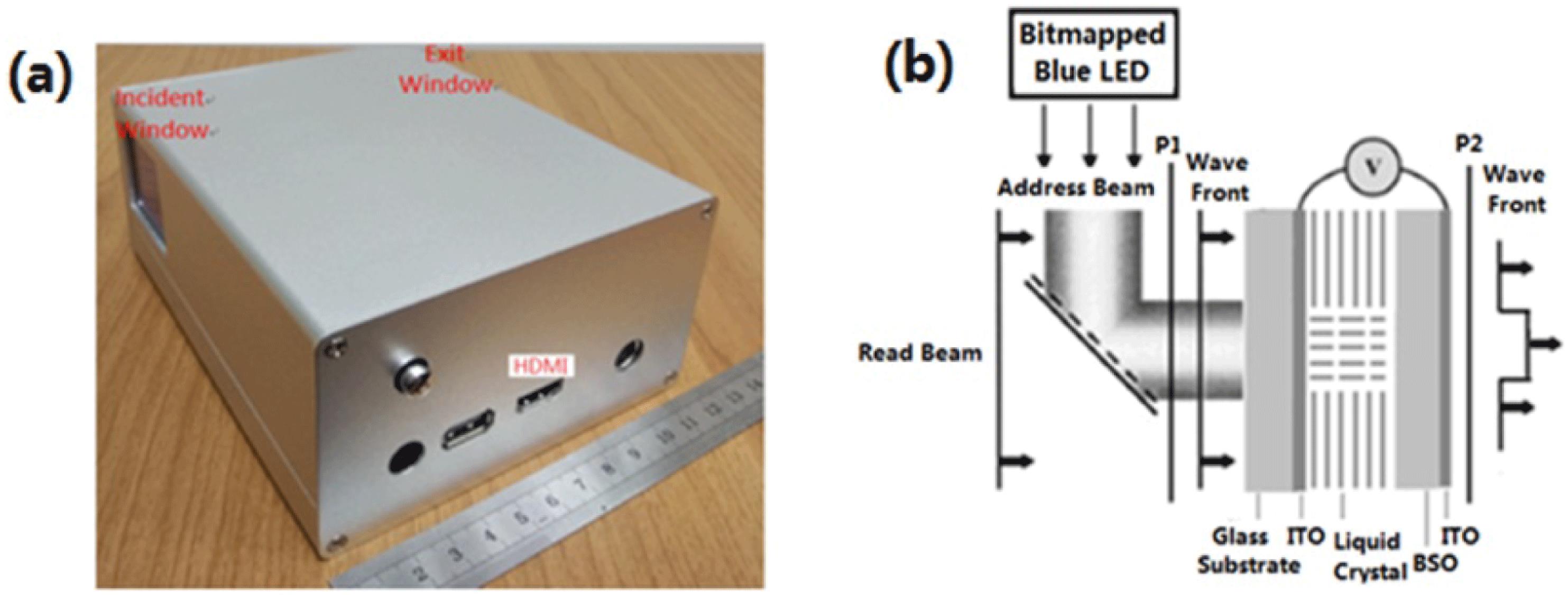
In addition to the liquid crystal material, the working principle of this phase type device is the same as the amplitude type device[ ) crystal, the voltage on the crystal will change when the projected blue light intensity changes. It will also lead to the change of voltage on the liquid crystal layer. Different modes of the liquid crystal result in different kinds of modulators. The amplitude-type device usually adopts the twisted nematic mode, while the phase-type device usually adopts the nematic mode. For the phase-type modulator in this paper, different voltages on the liquid crystal layer will lead to different phase delays. This means that the phase delay will change when the blue light intensity on the modulator changes. As a result, we can control the wavefront of 1053 nm laser beam if the blue light intensity distribution can be adjusted precisely.
Both the device and its working principle have been shown in Figure  , which can be divided into
  . Its maximum transmittance is about 90% for 1053 nm wavelength and the damage threshold of this device is estimated to be
  for 12 ns@1 Hz laser pulse.
3 Measurement and verification of the gray-phase curve
The optical setup has been shown in Figure ’. Figure
Based on the result mentioned above, the device can generate different phase modulations by loading the corresponding bitmap. As a result, in order to accurately control the phase distribution, we must know the relationship between the gray level of bitmap and the phase delay of the device. Since the wavefront sensor can only measure the phase distribution, not the absolute value of the phase, we design the method as described below.
The loaded bitmap is set according to the formula
 (1)
(1) has been shown in Figure
 In order to verify the accuracy of the curve shown in Figure  will be different. When the parameter
  changes, the phase difference between the edge and the central region will change. Different parameter
  means different range of gray level in the gray-phase curve. Theoretically, when the parameter
  increases, the range of the gray-phase curve will become shorter, but it should always be part of the curve shown in Figure
  is 0.1, 0.2, 0.3, 0.4, 0.5 and 0.6, respectively.
Figure  is different. These curves are basically coincident, which fully proves the accuracy of the gray-phase curve shown in Figure
4 Realization of special phase distribution
Two-dimensional phase distribution will be designed according to the formula
 (2)
(2)Designed and measured phase distributions in three cases with different parameter  have been shown in Figure
5 Conclusion
The above-mentioned experimental results show that the phase shaping accuracy of this device is high. If further feedback control is carried out, the actual modulation effect can be more ideal. At present, the maximum phase delay is about  for 1053 nm wavelength and the maximum region is
  . Our next goal is to develop a phase-type spatial light modulator with larger phase delay and larger region.
References
[1] J. A. Davis, D. E. McNamara, D. M. Cottrell, T. Sonehara. Appl. Opt., 39, 1549(2000).
[2] D. Mcgloin, G. Spalding, H. Melville, W. Sibbett, K. Dholakia. Opt. Express, 11, 158(2003).
[3] C. Maurer, A. Jesacher, S. Bernet, M. Ritsch-Marte. Laser Photonics Rev., 5, 81(2011).
[4] L. Hu, L. Xuan, Y. Liu, Z. Cao, D. Li, Q. Mu. Opt. Express, 12, 26(2004).
[5] N. Chattrapiban, E. A. Rogers, D. Cofield, W. T. Hill, R. Roy. Opt. Lett., 28, 22(2003).
[6] J. C. Vaughan, T. Hornung, T. Feurer, K. A. Nelson. Opt. Lett., 30, 3(2005).
[10] https://www.rdmag.com/article/2012/06/2012-r-d-100-award-winners
[11] J. Heebner, M. Borden, P. Miller, C. Stolz, T. Suratwala, P. Wegner, M. Hermann, M. Henesian, C. Haynam, S. Hunter, K. Christensen, N. Wong, L. Seppala, G. Brunton, E. Tse, A. Awwal, M. Franks, E. Marley, K. Williams, M. Scanlan, T. Budge, M. Monticelli, D. Walmer, S. Dixit, C. Widmayer, J. Wolfe, J. Bude, K. McCarty, J. M. DiNicola. Proc. SPIE, 7842(2010).
[12] D. Huang, W. Fan, X. Li, Z. Lin. Chin. Opt. Lett., 11, 072301(2013).
[13] D. Huang, W. Fan, X. Li, Z. Lin. Proc. SPIE, 8556(2012).
[14] D. Huang, W. Fan, P. Zhang, J. Li, S. Tang, Y. Guo, X. Li, Z. Lin. Infrared Eng., 45(2016).

Set citation alerts for the article
Please enter your email address
© Copyright 2018-2021 | Chinese Laser Press. All Rights Reserved 沪ICP备15018463号-20